Hybrid jet/electric vtol aircraft

a hybrid jet and electric technology, applied in the direction of aircraft navigation control, vertical landing/take-off aircraft, canard-type aircraft, etc., can solve the problems of inefficient high thrust loading and thrust inefficiency of prior art vectored thrust vtol aircraft in forward flight, and achieve high thrust loading, high thrust force, and thrust capability

Active Publication Date: 2013-03-14
SONIC BLUE AEROSPACE
View PDF13 Cites 126 Cited by
  • Summary
  • Abstract
  • Description
  • Claims
  • Application Information

AI Technical Summary

Benefits of technology

[0028]A hybrid VTOL jet-electric air vehicle as per the invention allows the thrust capability of the engine to be more closely matched to the thrust required to achieve efficient horizontal flight for the airframe of the vehicle in which the engine is installed. Prior art vectored thrust VTOL aircraft have suffered thrust inefficiencies in forward flight because the engine thrust requirements have been set by the requirements to achieve VTOL using vectored thrust (whether vectored thrust alone or vectored thrust augmented by a mechanically shaft-driven lift fan).
[0029]The thrust required to achieve VTOL using vectored thrust has uniformly been substantially in excess of the thrust required to achieve efficient forward flight because the conversion of thrust from the gas turbine engine to lifting force has been relatively inefficient (because the lifting forces are concentrated in one or more jet thrust columns and in one column of lift fan discharge, and very high thrust forces are required to achieve VTOL—hence, inefficient high thrust loadings). With the current invention, in contrast, because the electrical system and the lift fans are able to achieve high efficiencies in converting the power from the gas turbine engine to lift thrust and because the lifting forces are widely spread at lower velocities and at greater fan thrust efficiencies (due to lower fan loadings), less thrust capacity is required from the gas turbine engine to achieve VTOL, and thus the gas turbine engine may be sized more appropriately to the requirements of the airframe to achieve efficient forward flight.
[0030]Also advantageously, the use of multiple electric lift fans distributed throughout the airframe of the vehicle enables the vehicle to achieve greater stability in VTOL operations than was previously possible. In the prior art, in-service VTOL aircraft have utilized only two “columns” of lift thrust—both columns being in the centerline of the aircraft (in the case of JSF) or immediately adjacent to the centerline (in the case of the Harrier). One experimental aircraft (the Ryan X-5A) utilized three columns—one on the centerline and one in each of the two wings. Aircraft in the prior art depended upon all columns of thrust for safe operation in VTOL. A VTOL aircraft per the invention, in contrast, provides a level of redundancy that permits the loss of thrust from one or more fans without compromising the aircraft.
[0031]Further advantageously, now there is a fixed wing VTOL aircraft which does not have the constraints of high heat and high exhaust gas velocities in ground effect, as now the gas is ambient air temperature, traveling at low velocity and low temperature. Thus the air vehicle of the invention can take off and land from unprepared surfaces (tarmac, dirt, and grass), unlike certain VTOL aircraft in the prior art (e.g., Harrier, JSF, XV-5A / B, and Yakolev), which must use specially prepared reinforced surfaces. The vehicle of the invention shows distinct advantages over prior art VTOL vehicles offering low average downwash velocity from its distributed fan system for VTOL lift.
[0032]A vehicle according to the invention operates in VTOL with residual exhaust gas temperatures of 400-600 degrees Fahrenheit, and exhaust velocities of 300-600 feet per second, as compared to exhaust gas flow in prior art VTOL aircraft of 1200-1400 degrees Fahrenheit and exhaust gas velocities of over 2000 feet per second. Reduced exhaust temperatures due to engine power extraction are a decided advantage in the new concept, as the invention reduces airborne debris from lower exhaust flow and ambient VTOL lift from the electric fans, eases operation of personnel around the air vehicle providing a safer lift-off environment, and reduces fire hazards due to lower temperature exhaust and downward jet exhaust environment.

Problems solved by technology

Prior art vectored thrust VTOL aircraft have suffered thrust inefficiencies in forward flight because the engine thrust requirements have been set by the requirements to achieve VTOL using vectored thrust (whether vectored thrust alone or vectored thrust augmented by a mechanically shaft-driven lift fan).
The thrust required to achieve VTOL using vectored thrust has uniformly been substantially in excess of the thrust required to achieve efficient forward flight because the conversion of thrust from the gas turbine engine to lifting force has been relatively inefficient (because the lifting forces are concentrated in one or more jet thrust columns and in one column of lift fan discharge, and very high thrust forces are required to achieve VTOL—hence, inefficient high thrust loadings).

Method used


Image

  • Hybrid jet/electric vtol aircraft
  • Hybrid jet/electric vtol aircraft
  • Hybrid jet/electric vtol aircraft

Examples


Embodiment Construction

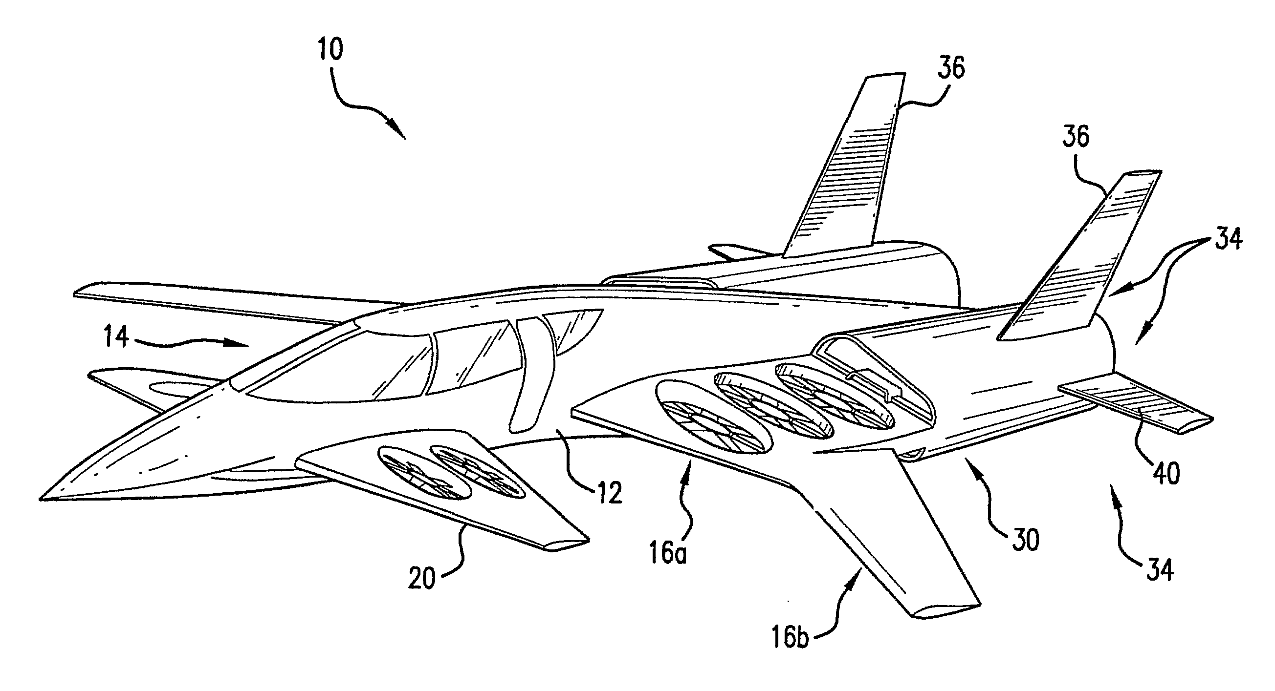
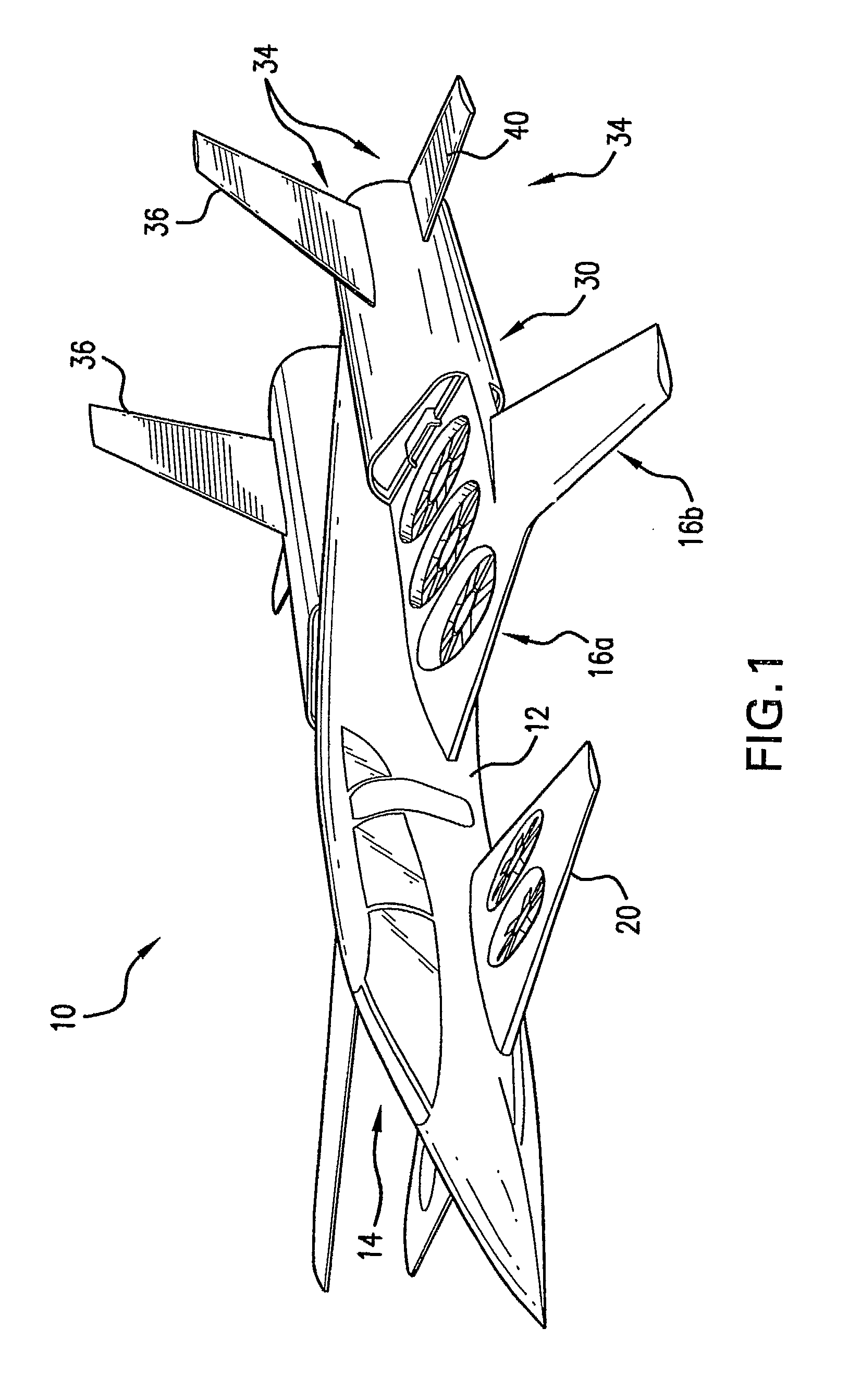
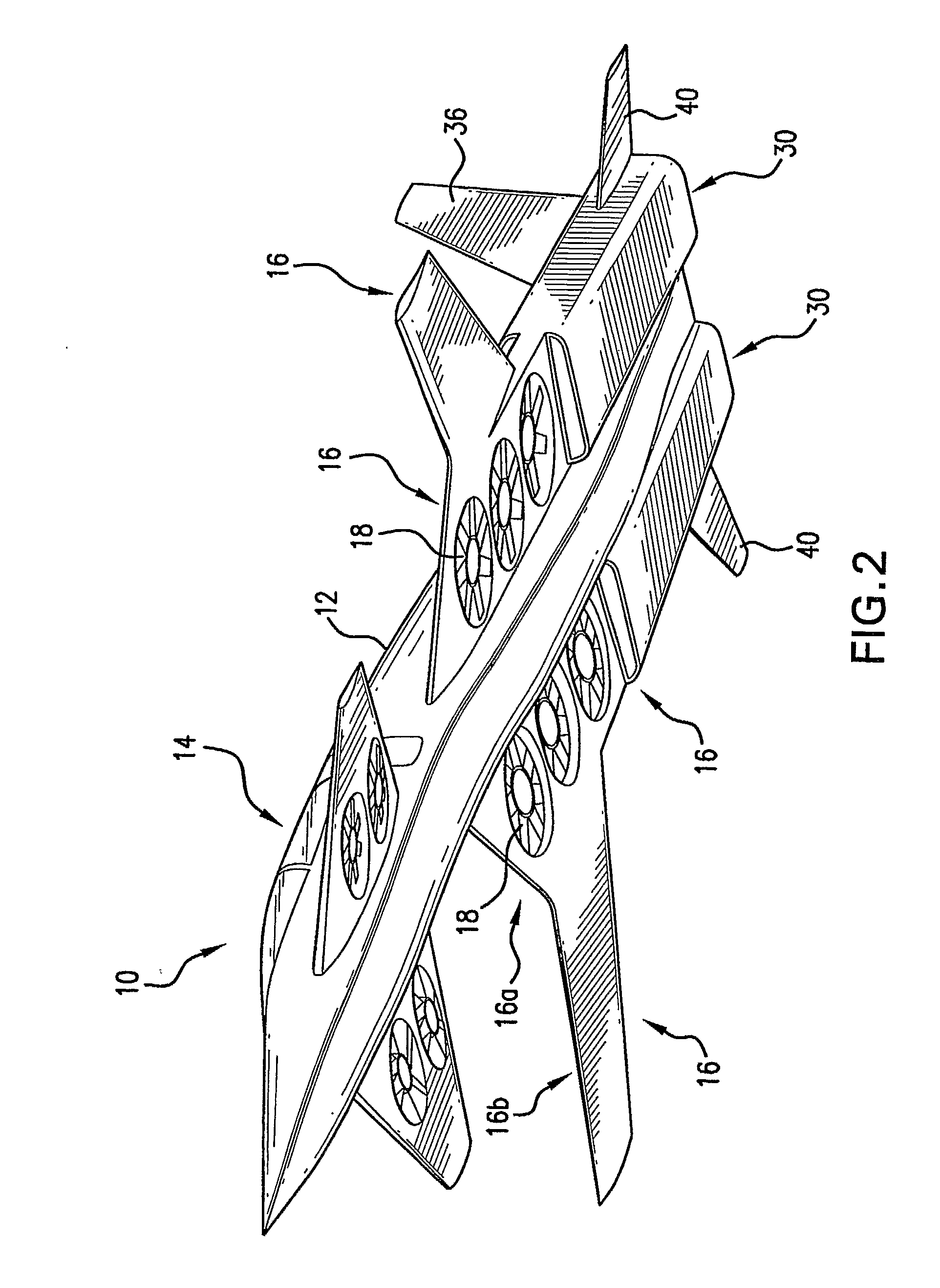
[0042]The overall configuration of a manned embodiment 10 of an aircraft incorporating a lift / propulsion system according to the invention is illustrated in FIGS. 1-5. The aircraft 10 has a fuselage 12 with a cockpit / cabin 14. The main wing portion 16 of the aircraft 10 extends from about the lengthwise mid-point of the fuselage 12 to the rear of the aircraft 10. Each main wing has a generally rectangular root portion 16a, with a rearward-swept leading edge 18, and a forward-swept, outboard wing extension portion 16b. (The root portion 16a is actually a strake that can be thought of as part of the fuselage.) This forward-sweep configuration of the main wings provides enhanced maneuverability and control, particularly during VTOL and transition to forward flight.

[0043]In addition to the main wing portion 16, the aircraft 10 includes canards 20 extending from the fuselage 12 and located lengthwise generally proximate the cockpit / cabin 14. The canards 20 provide additional lift and enh...


PUM


Abstract

A fixed-wing VTOL aircraft features an array of electric lift fans distributed over the surface of the aircraft. A generator is (selectively) coupled to the gas turbine engine of the aircraft. During VTOL operation of the aircraft, the engine drives the generator to generate electricity to power the lifting fans. Power to the lifting fans is reduced as the aircraft gains forward speed and is increasingly supported by the wings.

Description

CROSS-REFERENCE TO RELATED APPLICATIONS[0001]This application claims priority benefit of provisional U.S. applications 60 / 673,166 filed Apr. 20, 2005, and 60 / 695,690 filed Jun. 30, 2005, the contents of each of which is incorporated by reference in the entirety.FIELD OF THE INVENTION[0002]The invention relates to vertical take-off and landing (VTOL) or short take-off / vertical landing (STOVL) aircraft. (The term “VTOL” will be used hereafter to refer to VTOL or STOVL.) More particularly, the invention relates to fixed-wing VTOL aircraft.BACKGROUND OF THE INVENTION[0003]In general, two types of VTOL aircraft have been built and flown successfully: 1) rotary wing aircraft (helicopters) and 2) vectored-thrust, fixed-wing aircraft (e.g., the Harrier “Jump-Jet” and the JSF Joint Strike Fighter), in which the thrust generated by a turbojet engine is vectored downwardly for lift-off and then re-directed horizontally for wing-supported forward flight. Tilt-rotor vehicles such as the V-22 Osp...

Claims


Application Information

Patent Timeline
Patent Type & Authority Applications(United States)
IPC IPC(8): B64C29/00B64C39/12
CPCB64C29/0025B64C39/12Y02T50/64Y02T50/44B64D27/24Y02T50/40Y02T50/60
Inventor LUGG, RICHARD H.YOUNGREN, HAROLD
Owner SONIC BLUE AEROSPACE
Why Eureka
Try Eureka