
Forming a ferromagnetic alloy core for high frequency micro fabricated inductors and transformers

a technology of microfabricated inductors and transformers, applied in the direction of transformers/inductances magnetic cores, magnets, magnetic bodies, etc., can solve the problem of linear reduction of inductance, and achieve the effect of reducing eddy current loss

Active Publication Date: 2013-03-14
TEXAS INSTR INC
View PDF6 Cites 8 Cited by
  • Summary
  • Abstract
  • Description
  • Claims
  • Application Information

AI Technical Summary

Benefits of technology

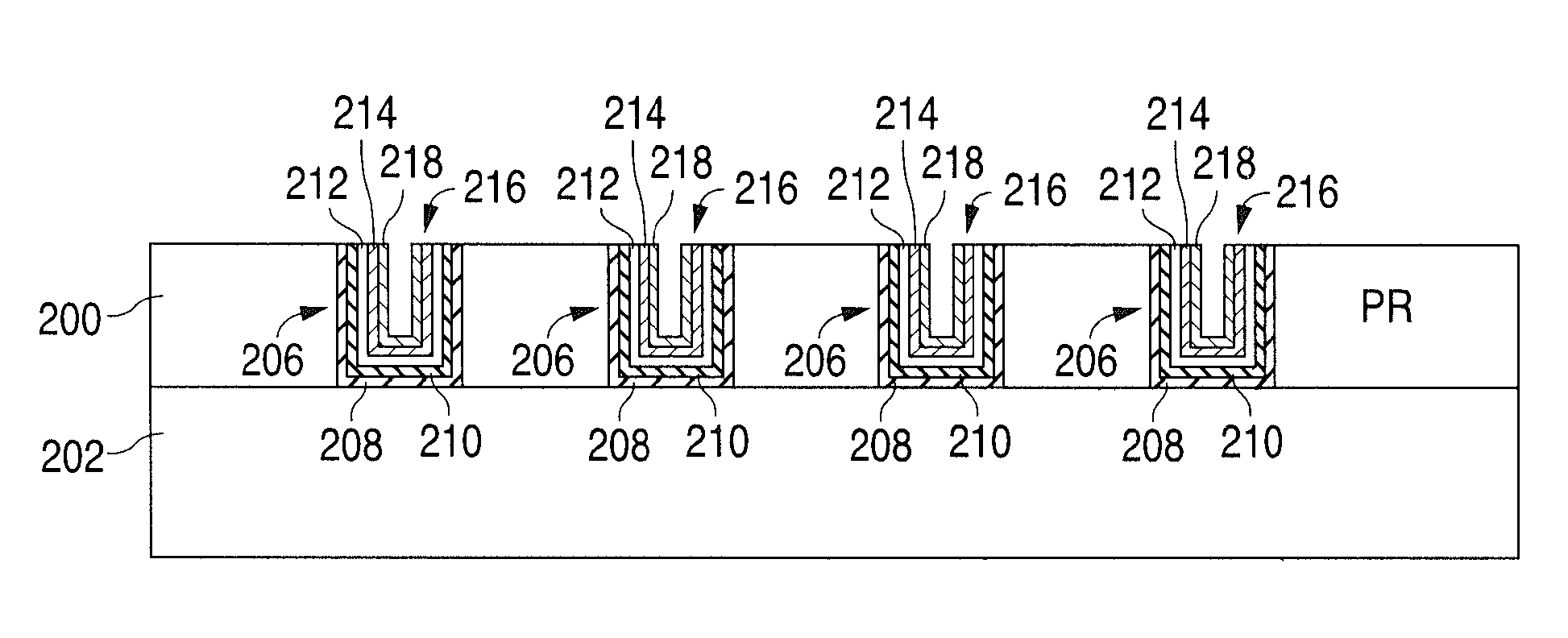
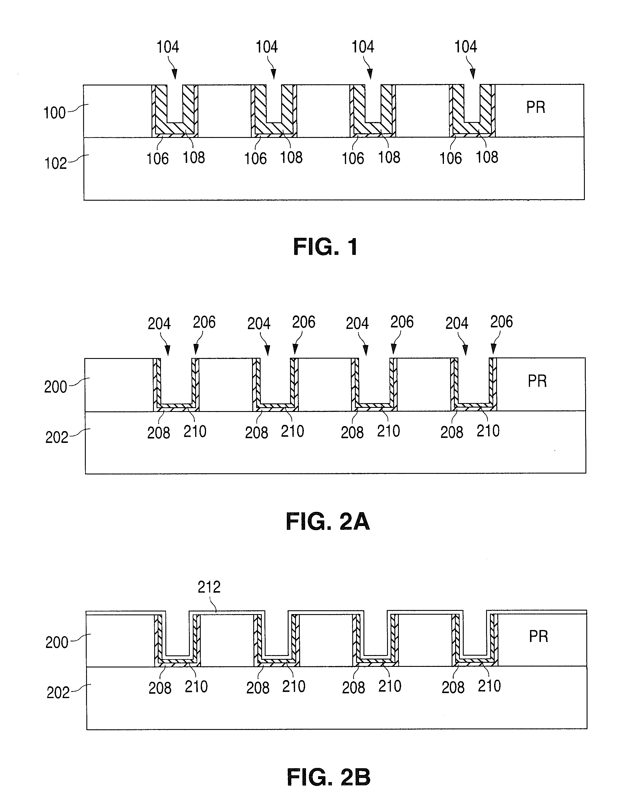
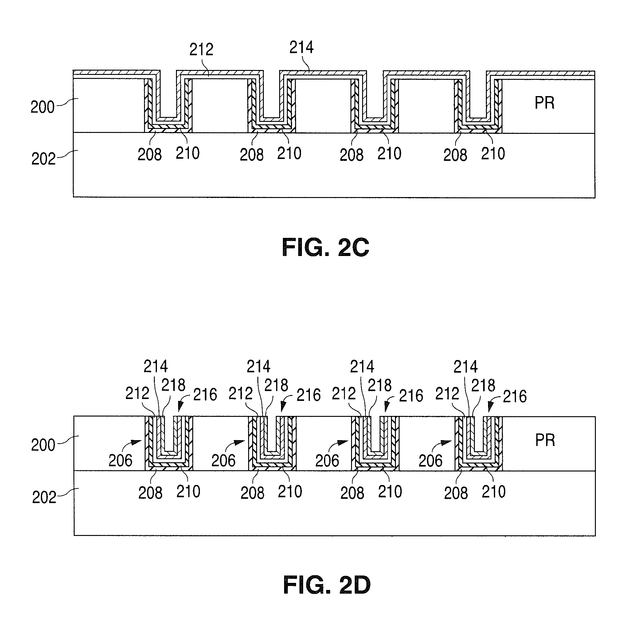
The patent describes a method of creating a laminated ferromagnetic alloy core for micro-fabricated inductors and transformers. By using multiple thin layers within deep patterns in non-removable photoresist film, the method provides sufficient volume of magnetic material for high frequency applications while reducing eddy current loss. The technical effect is to improve the performance of micro-fabricated inductors and transformers in high-frequency applications.

Problems solved by technology

However, this has the undesirable effect of reducing the cross-sectional area of the magnetic core which, in turn, linearly reduces the inductance.

Method used


Image

  • Forming a ferromagnetic alloy core for high frequency micro fabricated inductors and transformers
  • Forming a ferromagnetic alloy core for high frequency micro fabricated inductors and transformers
  • Forming a ferromagnetic alloy core for high frequency micro fabricated inductors and transformers

Examples


Embodiment Construction

[0010]Illustrative embodiments of the invention are described below. In the interest of clarity, not all features of an actual implementation are described in this specification. It will of course be appreciated that in the development of any such actual implementation, numerous specific decisions must be made to achieve the designer's specific goals, such as compliance with system-related and business-related constraints, which will vary from one implementation to another. Moreover, it will be appreciated that such a development effort might be complex and time-consuming, but would nevertheless be a routine undertaking for those of ordinary skill in the art having the benefit of this disclosure.

[0011]The present subject matter will now be described with reference to the attached drawings. Various structures and methods are schematically depicted in the drawings for purposes of explanation only and so as not to obscure the present disclosure with details that are well known to those...


PUM

PropertyMeasurementUnit
Dielectric polarization enthalpyaaaaaaaaaa
Currentaaaaaaaaaa
Electrical conductoraaaaaaaaaa

Abstract

A plurality of sequential electro-deposition, planarization and insulator deposition steps are performed over a patterned thick photoresist film to form a laminated ferromagnetic alloy core for micro-fabricated inductors and transformers. The use of a plurality of contiguous thin laminations within deep patterns on non-removable photoresist film provides sufficient volume of magnetic film in, for example, high frequency applications, and reduces eddy current loss at high frequency.

Description

RELATED APPLICATION[0001]This application is related to co-pending and commonly-assigned U.S. patent application Ser. No. [Attorney Docket No. NSC1-N5000 [P07683]], filed on Sep. 12, 2011, and titled “A Method of Selectively Etching a Conductive Seed Layer in the Damascene Electroplating of Magnetic Alloy Laminations.” Application Ser. No. [Attorney Docket No NSC1-N5000 [P07682]].FIELD OF THE INVENTION[0002]The present invention relates generally to integrated circuit technology and, in particular, to the formation of a ferromagnetic alloy core for high frequency micro-fabricated inductors and transformers utilizing multiple electro-deposition and chemical mechanical polishing (CMP) steps over a patterned thick photoresistive film.BACKGROUND OF THE INVENTION[0003]Among the known methods for forming laminations in micro-fabricated high frequency inductors and transformers, the utilization of thick, non-removable photoresist (PR) is the most efficient since it provides a high volume o...

Claims


Application Information

Patent Timeline
IPC IPC(8): H01L29/02H01L21/02
CPCH01L28/10H01L23/5227Y10T29/49075H01F41/34Y10T29/49078H01F27/24H01L2924/0002H01L2924/00
Inventor HOPPER, PETER J.FRENCH, WILLIAMPAPOU, ANDREILEE, DOK WON
Owner TEXAS INSTR INC
Learn More