
Engine cranking motor soft-start system and method

Inactive Publication Date: 2013-03-14
ENERPRO
View PDF5 Cites 11 Cited by
  • Summary
  • Abstract
  • Description
  • Claims
  • Application Information

AI Technical Summary

Benefits of technology

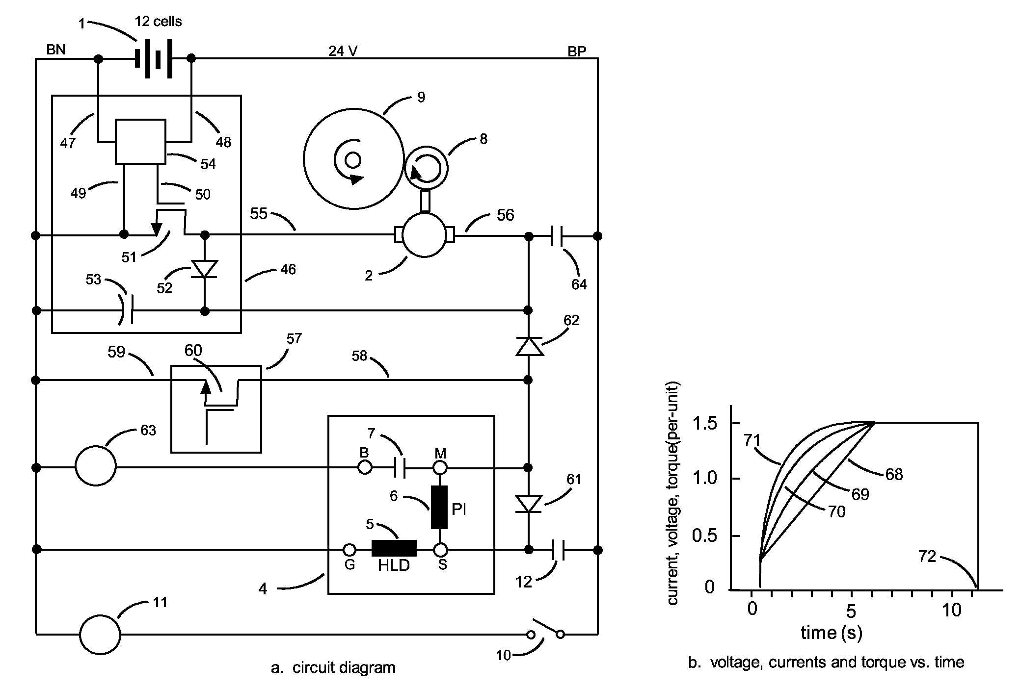
The present invention relates to a system and method for starting an engine using an electric cranking motor. The system includes a switching power converter that gradually increases the voltage across the cranking motors to increase their service life and decrease the likelihood of aborted starts caused by gear abutment. The system also uses ramp voltage instead of step voltage to reduce the current and torque required to accelerate the engine, and eliminates the need for a surge rated resistor. The power converter allows for the use of twin motors in a high-speed cranking system, reducing motor cost and increasing speed capability. These technical effects improve the reliability and performance of the engine starting system.

Problems solved by technology

High fuel costs and increasingly strict air pollution regulations have increased the frequency of engine starts in diesel-powered locomotives, highway trucks and off-road vehicles.
More engine starts have increased the failure rate of the cranking motors and gears used to start these large engines.
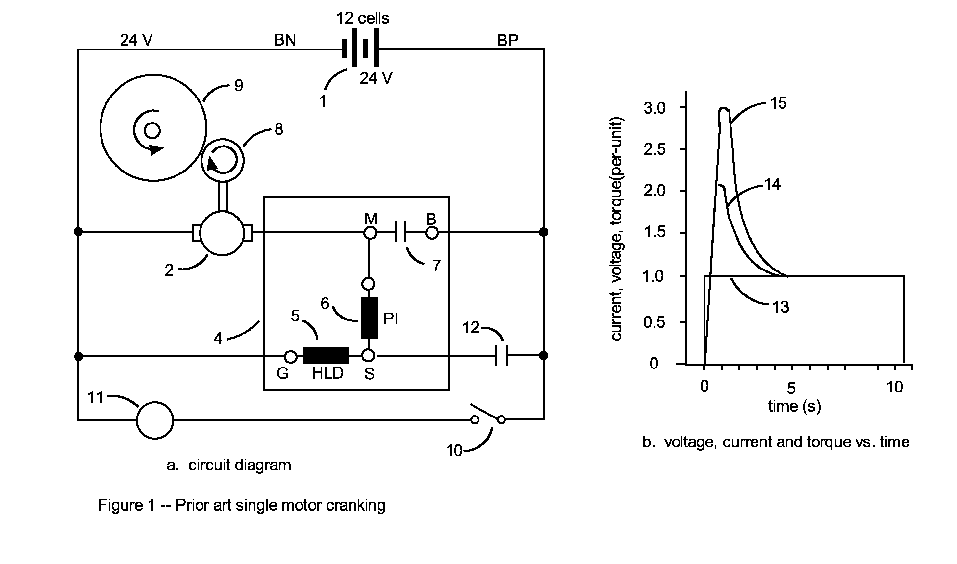
Avoiding a sticking abutment by spinning the pinion gear before it engages the ring gear is problematic because: 1) high motor friction may result in insufficient torque to break the abutment, and 2) compensating for high friction by reducing the resistance between the battery and motor may result in motor over-speed if the pinion gear fails to move because of a stuck solenoid plunger.
High initial current burns the cranking motor commutator bars and carbon brushes, and high initial torque accelerates the wear-out of the pinion and ring gears as well as the motor nose bearing.
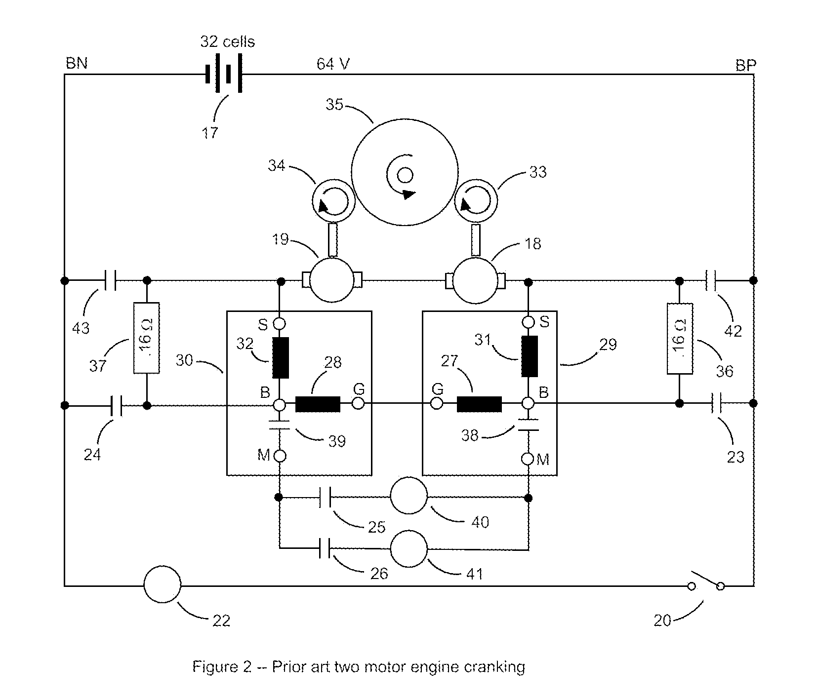
Two-motor cranking does not permit the solenoid contacts to be used for connecting the motor to the battery.
As before, peak current and torque can reach damaging levels with each engine start.

Method used


Image

  • Engine cranking motor soft-start system and method
  • Engine cranking motor soft-start system and method
  • Engine cranking motor soft-start system and method

Examples


Embodiment Construction

[0039]The present engine cranking motor soft-start system is designed to increase the cranking motor service life by using power electronics to limit the acceleration of the engine, and thereby reduce the cranking motor's peak current and torque. One primary application relates to diesel-electric locomotive engines formerly manufactured by the Electro-Motive Division of the General Motors Corporation, and more recently by the Electro-Motive Diesel Division of the Caterpillar Corporation. These locomotives use two 32 V series-wound cranking motors connected in series, which are powered by a 32 cell 64 V lead-acid battery with a typical capacity of 500 A-h.

[0040]The acceleration of the engine being started is limited by using a switching power converter to gradually ramp up the voltage across the cranking motor. When implemented as described herein, the use of a switching power converter in this way serves to reduce peak cranking motor current and peak cranking motor torque, enables t...


PUM


Abstract

An engine cranking motor soft-start system and method includes at least one cranking motor and a switching power converter which is coupled to the cranking motors such that the voltage across the motors varies with the converter's duty cycle. The duty cycle, and thereby the voltage across the motors, is gradually increased over a predetermined period. This serves to limit the acceleration of the cranking motors, and thereby their peak current and torque, which may serve to increase their service life. The cranking motors are typically operatively coupled to drive respective pinion gears which are brought into engagement with a ring gear when starting the engine. The system is preferably arranged such that the gradually increasing duty cycle results in the torque of the cranking motors being sufficient to break an abutment that may be present between the pinion gears and the ring gear.

Description

RELATED APPLICATIONS[0001]This application claims the benefit of provisional patent application No. 61 / 532,242 to Bourbeau, filed Sep. 8, 2011.BACKGROUND OF THE INVENTION[0002]1. Field of the Invention[0003]This invention relates to the field of engine cranking motors, and particularly to systems and methods for soft-starting cranking motors used in diesel-electric locomotive engines.[0004]2. Description of the Related Art[0005]High fuel costs and increasingly strict air pollution regulations have increased the frequency of engine starts in diesel-powered locomotives, highway trucks and off-road vehicles. More engine starts have increased the failure rate of the cranking motors and gears used to start these large engines.[0006]Engines of this sort typically have one or two cranking motors. A schematic diagram for a conventional ‘contactor-switched hard-start’ system using one cranking motor is shown in FIG. 1a. A 24 volt battery 1 powers the system, which includes a 24 volt cranking...

Claims


Application Information

Patent Timeline
IPC IPC(8): F02N11/08
CPCF02N11/0851F02N15/06F02N2300/108F02N2300/104F02N2300/102
Inventor BOURBEAU, FRANK J.
Owner ENERPRO
Learn More