Magnetic recording head, manufacturing method thereof, and magnetic disk device

Inactive Publication Date: 2013-03-14
HITACHI LTD
View PDF8 Cites 27 Cited by
  • Summary
  • Abstract
  • Description
  • Claims
  • Application Information

AI Technical Summary

Benefits of technology

[0026]According to the present invention, the electrode of the non-magnetic material is extended to the end of the magnetic pole. This makes it possible to prevent the resistance variation due to the AMR effect or the eddy current, and to stabilize

Problems solved by technology

This leads to the requirement of further micro fabrication of the magnetic recording head.
As a result, sufficient magnetic field may not be obtained to record data to the magnetic recording medium.
However, the configuration of the existing write head is different from the configuration of the microwave-assisted magnetic recording.
For this reason, there are three important problems in the supply of the current.
The first problem is the variation of the resistance due to the anisotropic magneto-resistance (AMR) effect (hereinafter referred to as the AMR effect) or the eddy current.
There is a risk that the resistance of the magnetic film material may vary due to the AMR effec

Method used


Image

  • Magnetic recording head, manufacturing method thereof, and magnetic disk device
  • Magnetic recording head, manufacturing method thereof, and magnetic disk device
  • Magnetic recording head, manufacturing method thereof, and magnetic disk device

Examples


first embodiment

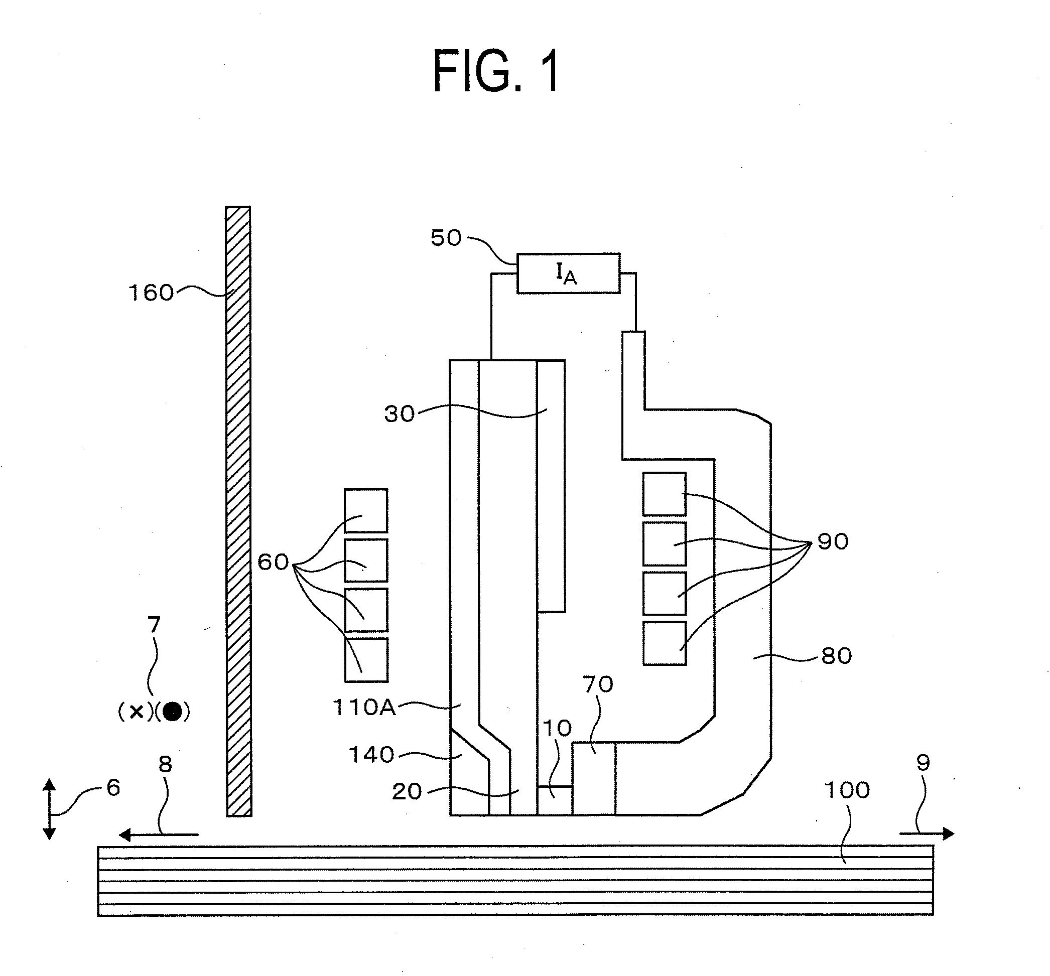
[0049]FIG. 1 shows the configuration of a magnetic recording head including a spin torque oscillator.

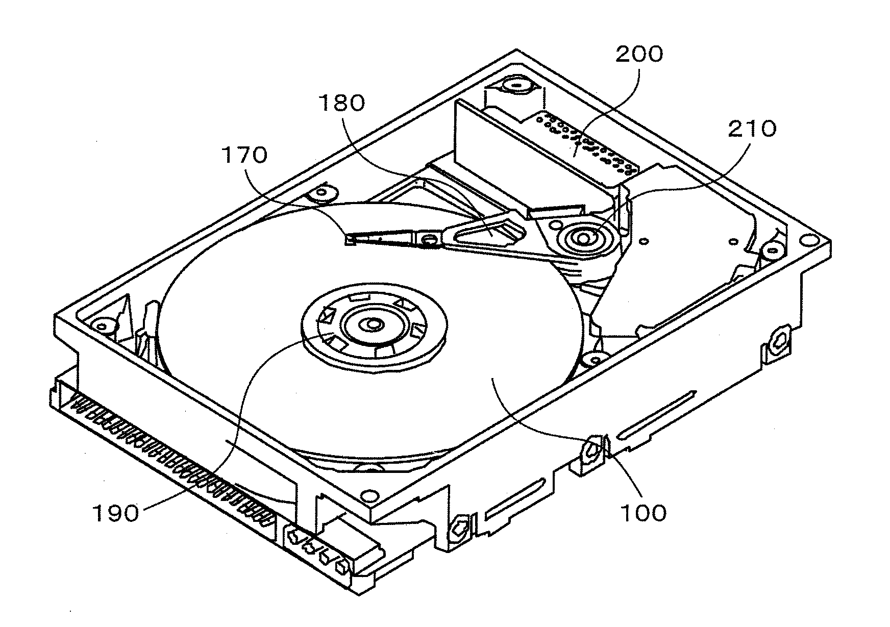
[0050]In FIG. 1, reference numeral 10 denotes a spin torque oscillator, 20 denotes a main pole, 30 denotes a yoke magnetic film, 50 denotes a current source, 60 denotes a lower coil, 70 denotes a trailing shield, 80 denotes a sub pole, 90 denotes an upper coil, 100 denotes a magnetic recording medium, 110A denotes a shield gap film, 140 denotes a leading edge shield, and 160 denotes a base for supporting the magnetic recording head.

[0051]In FIG. 1, an arrow 8 indicates the moving direction of the head with respect to the medium 100, while an arrow 9 indicates the moving direction of the medium 100 with respect to the head. For the simplification of the expression in the following description, the direction of the arrow 8 is expressed as “lower part”, or “lower side” or “bottom side”, while the direction of the arrow 9 is expressed as “upper part”, or “upper side” or “top side”. Thus,...

second embodiment

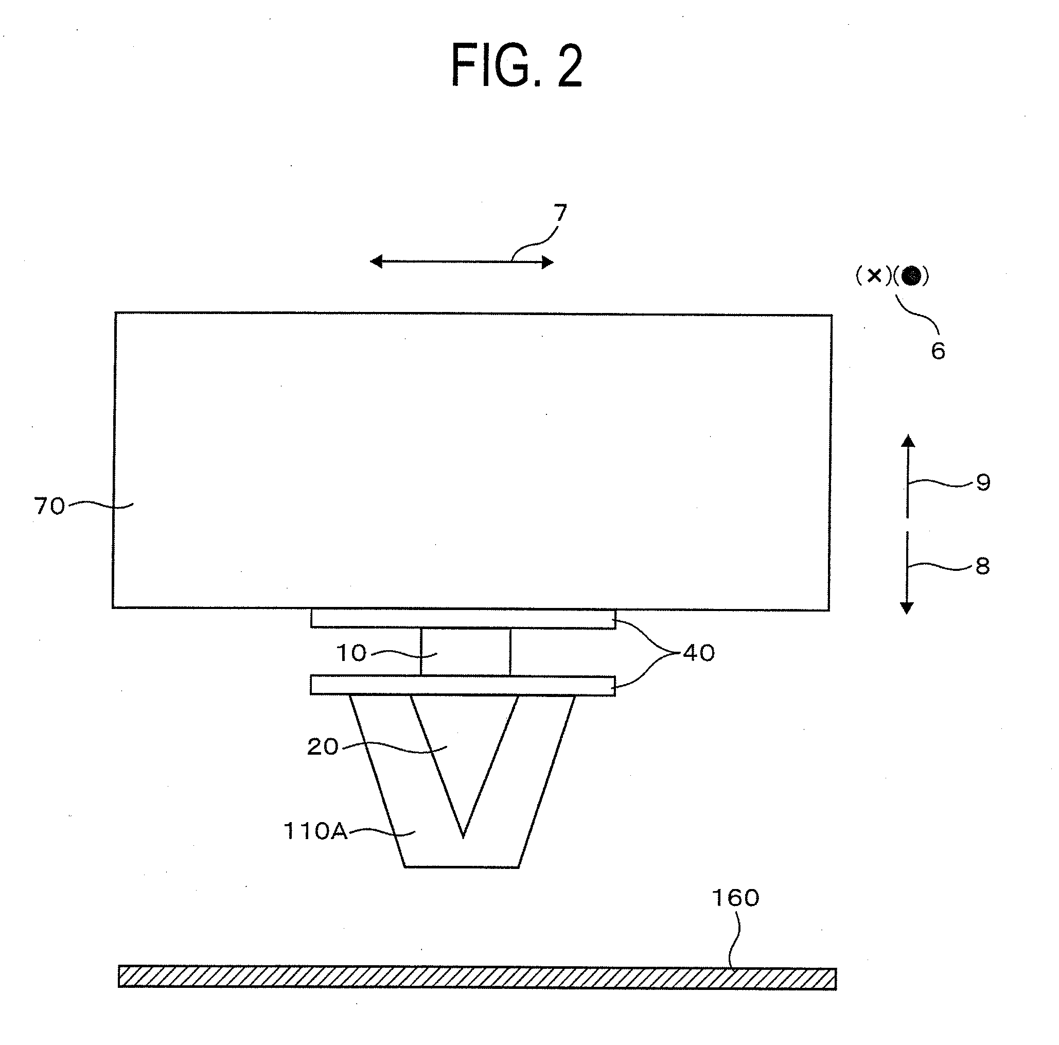
[0067]FIG. 7 is a schematic cross-sectional view of the surface including the spin torque oscillator 10 in the head moving direction 8 of a magnetic recording head according to a second embodiment of the present invention. The configuration is such that the yoke magnetic film 30 is provided in the lower part of the main pole 20, and that the non-magnetic electrode 40 is provided in the upper part of the main pole 20. In this way, it is possible to form the non-magnetic electrode 40 and the upper coil 90 at the same time. Thus, the number of steps is expected to be reduced from the point of view of the process.

third embodiment

[0068]FIG. 8A is a schematic cross-sectional view of the surface including the spin torque oscillator 10 in the head moving direction 8 of a magnetic recording head according to a third embodiment of the present invention. The configuration is such that the non-magnetic electrode 40 is provided in the upper part of the recording head, but not in the lower part thereof.

[0069]In the first and second embodiments, the non-magnetic electrode 40 is provided on the outside of the main pole 20 or the shield gap film 110A. However, in the first and second embodiments, the magnetic material (the sub pole 80) is used as the line on the upper side of the recording head, leading to the variation of the line resistance due to the AMR effect or the eddy current. Thus, in this embodiment, the configuration is such that the non-magnetic line 40 is provided on the upper side of the recording head.

[0070]In FIGS. 6A to 6E of the first embodiment, the non-magnetic electrode 40 of the third embodiment is...


PUM

PropertyMeasurementUnit
Electrical resistanceaaaaaaaaaa

Abstract

A magnetic recording head used for microwave-assisted magnetic recording includes: a main pole; a spin torque oscillator provided on the main pole, including a high-speed rotating magnetization layer in which the magnetization is rapidly rotated by a spin torque; a trailing shield provided on the spin torque oscillator; and a sub pole magnetically coupled to the trailing shield provided in a medium-facing surface, extending in a vertical direction to the medium-facing surface. Then, a non-magnetic electrode is provided on the outside of a trailing gap in which the spin torque oscillator is provided with respect to a magnetic material of the main pole, the trailing shield, or the sub pole, to prevent the line resistance variation due to the AMR effect or the eddy current. Thus, the variation of the current flowing to the spin torque oscillator can be controlled to achieve stable oscillation.

Description

INCORPORATION BY REFERENCE[0001]The present application claims priority from Japanese application serial No. 2011-199211, filed on Sep. 13, 2011, the entire contents of which are hereby incorporated by reference into this application.FIELD OF THE INVENTION[0002]The present invention relates to a magnetic recording head, a manufacturing method thereof, and a magnetic disk device. More particularly, the present invention relates to a magnetic recording head including a spin torque oscillator in a microwave-assisted magnetic recording head system, a manufacturing method of the magnetic recording head, and a magnetic disk device including the magnetic recording head.BACKGROUND OF THE INVENTION[0003]In recent years, there is a demand for high recording density in hard disk drives (HDD) with a rapid growth of about 40% per year. In order to achieve such a high growth rate, it is necessary to write data to a magnetic recording medium with smaller track width and bit length. This leads to t...

Claims


Application Information

Patent Timeline
IPC IPC(8): G11B5/127G11B5/187G11B21/02
CPCG11B5/187G11B5/1278Y10T29/49032G11B2005/0024G11B5/3146
Inventor UDO, YUTAWATANABE, KATSURO
Owner HITACHI LTD
Why Eureka
Try Eureka