Optical waveguide device

a waveguide and optical waveguide technology, applied in the field of optical waveguide devices, can solve the problems of reducing the extinction ratio of the output, the complementarity of the on-light output and the off-light output, and the decrement of the on/off extinction ratio characteristic of the optical waveguide device, so as to suppress the problem, only derive radiation-mode light, and suppress the effect of the generation of unnecessary higher-mode ligh

Active Publication Date: 2013-03-14
SUMITOMO OSAKA CEMENT CO LTD
View PDF9 Cites 9 Cited by
  • Summary
  • Abstract
  • Description
  • Claims
  • Application Information

AI Technical Summary

Benefits of technology

[0015]According to the first aspect, the optical waveguide device having a Mach-Zehnder type waveguide formed on a substrate, a slope of two waveguides input to an optical coupler on an output side of the Mach-Zehnder type waveguide is 0 degrees, a waveguide of the optical coupler after being coupled by the optical coupler is a multi-mode waveguide, and the waveguide which is output from the optical coupler is a three-branched waveguide including an output main waveguide and two output sub waveguides interposing the output main waveguide therebetween. Accordingly, it is possible to suppress generation of unnecessary higher-mode light in the optical coupler and to suppress the problem in that the higher-mode light enters the output main waveguide to fluctuate the output light. It is also possible to stably derive only the radiation-mode light by the use of the output sub waveguide.
[0016]According to the second aspect, since a thickness of the substrate is equal to or less than 15 times a wavelength of an optical wave propagating in the waveguide, the substrate serves as a slab waveguide and thus the optical wave radiated in the substrate propagates in the substrate and is easily re-coupled to the optical waveguide. By ...

Problems solved by technology

Accordingly, radiation-mode light which is OFF light is mixed into the output waveguide to cause a crosstalk phenomenon, thereby causing a problem in that the ON/OFF extinction ratio characteristic of the optical waveguide device degrades.
As a result, the extinction ratio of the output degrades or the complementarity of the ON-light output and the OFF-light output c...

Method used


Image

  • Optical waveguide device
  • Optical waveguide device
  • Optical waveguide device

Examples


Embodiment Construction

[0025]An optical waveguide device according to an embodiment of the invention will be described below in detail.

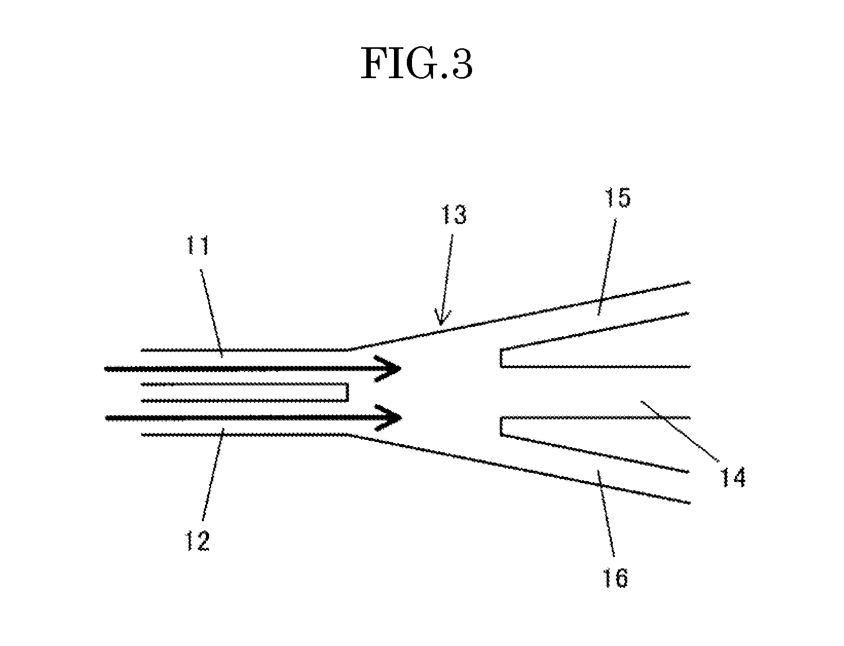
[0026]As shown in FIG. 3, an optical waveguide device according to an embodiment of the invention is an optical waveguide device having a Mach-Zehnder type waveguide formed on a substrate, in which a slope of two waveguides 11 and 12 input to an optical coupler 13 on an output side of the Mach-Zehnder type waveguide is 0 degrees, a waveguide of the optical coupler after being coupled by the optical coupler is a multi-mode waveguide, and the waveguide which is output from the optical coupler is a three-branched waveguide including an output main waveguide 14 and two output sub waveguides interposing the output main waveguide therebetween.

[0027]As shown in FIG. 3, it is possible to set the slopes of two waveguides input to the optical coupler 13 to 0 degrees by arranging the branched waveguides 11 and 12 to be parallel to each other, and it is possible to suppress generation...


PUM


Abstract

An optical waveguide device having a Mach-Zehnder type waveguide formed on a substrate is provided in which a slope of two waveguides input to an optical coupler on an output side of the Mach-Zehnder type waveguide is 0 degrees, a waveguide of the optical coupler after being coupled by the optical coupler is a multi-mode waveguide, and the waveguide which is output from the optical coupler is a three-branched waveguide including an output main waveguide and two output sub waveguides interposing the output main waveguide therebetween.

Description

BACKGROUND OF THE INVENTION[0001]1. Field of the Invention[0002]The present invention relates to an optical waveguide device and more particularly, to an optical waveguide device such as an optical modulator or an optical switch in which a Mach-Zehnder type waveguide is formed on a substrate.[0003]2. Description of Related Art[0004]In the fields of optical communications and optical measurements, an optical intensity modulator or an optical switch having an optical waveguide in which a Mach-Zehnder type (MZ type) structure is formed on a substrate of lithium niobate (LN), semiconductor material, or the like has been widely used.[0005]The optical modulator having the MZ type structure includes a modulation electrode disposed along an MZ type waveguide, changes the optical phase between branched waveguides (arms) of the MZ type waveguide with a voltage applied to the modulation electrode, and controls ON / OFF states of light on the basis of an interference phenomenon in an optical coup...

Claims


Application Information

Patent Timeline
IPC IPC(8): G02F1/035
CPCG02F2201/05G02B6/12007G02F2001/217G02F2001/212G02B6/122G02B6/29355G02F2202/20G02B6/29352G02F2201/06G02F1/212G02F1/217
Inventor ISHIKAWA, YASUHIROKONDOU, KATSUTOSHIMIYAZAKI, NORIKAZUOIKAWA, SATOSHI
Owner SUMITOMO OSAKA CEMENT CO LTD
Why Eureka
Try Eureka