Intra-pericardial medical device

a medical device and pericardial technology, applied in the field of implantable cardiac devices, can solve the problems of difficult placement of the left side, long or unpredictable amount of time needed for the implant, and a large portion of the patient population is unable to receive this type of treatment, so as to reduce the heating source of the rf, avoid eddy current flow, and avoid large force and torque

Active Publication Date: 2013-03-14
PACESETTER INC
View PDF1 Cites 33 Cited by
  • Summary
  • Abstract
  • Description
  • Claims
  • Application Information

AI Technical Summary

Benefits of technology

[0011]In accordance with one embodiment an implantable medical system is provided that includes an intra-pericardial medical device (IPMD) located in the intra-pericardial SAC. The IPMD includes a telemetry system integrated therein. The IPMD affords one or more of the following: i) free access to locations of the right atrium (RA), left atrium (LA), right ventricle (RV), and left ventricle (LV); ii) pacing/sensing based timing of any desired combination of the RA, RV, LA and LV; iii) reduces RF heating sources to provide a system that is MRI safe; iv) removes conductors from inside the myocardium, thereby avoiding the formation of

Problems solved by technology

Furthermore, the location of the coronary veins effects the implant location of the electrode, which can make it difficult to place a left side lead in a specific preferred location and may lengthen or render unpredictable the amount of time needed to implant the lead.
In addition, a portion of the patient population is unable to receive this type of lead due to vasculature anomalies.
Such placement techniques have disadvantages.
Moreover, cardiac leads for conventional implantable medical devices experience at least some of the following limitations.
Conventional cardiac leads afford limited access to only certain locations of the left atrium (LA) and left ventricle (LV) that are depend in part on vein location.
Conventional cardiac leads are limited to pacing/sensing based timing for only certain combinations of electrodes due to the electrodes proximity to the RA, RV, LA and LV.
Further, conventional cardiac leads create RF heating sources when in the presence of an MRI field if not corrected throu

Method used


Image

  • Intra-pericardial medical device
  • Intra-pericardial medical device
  • Intra-pericardial medical device

Examples


Embodiment Construction

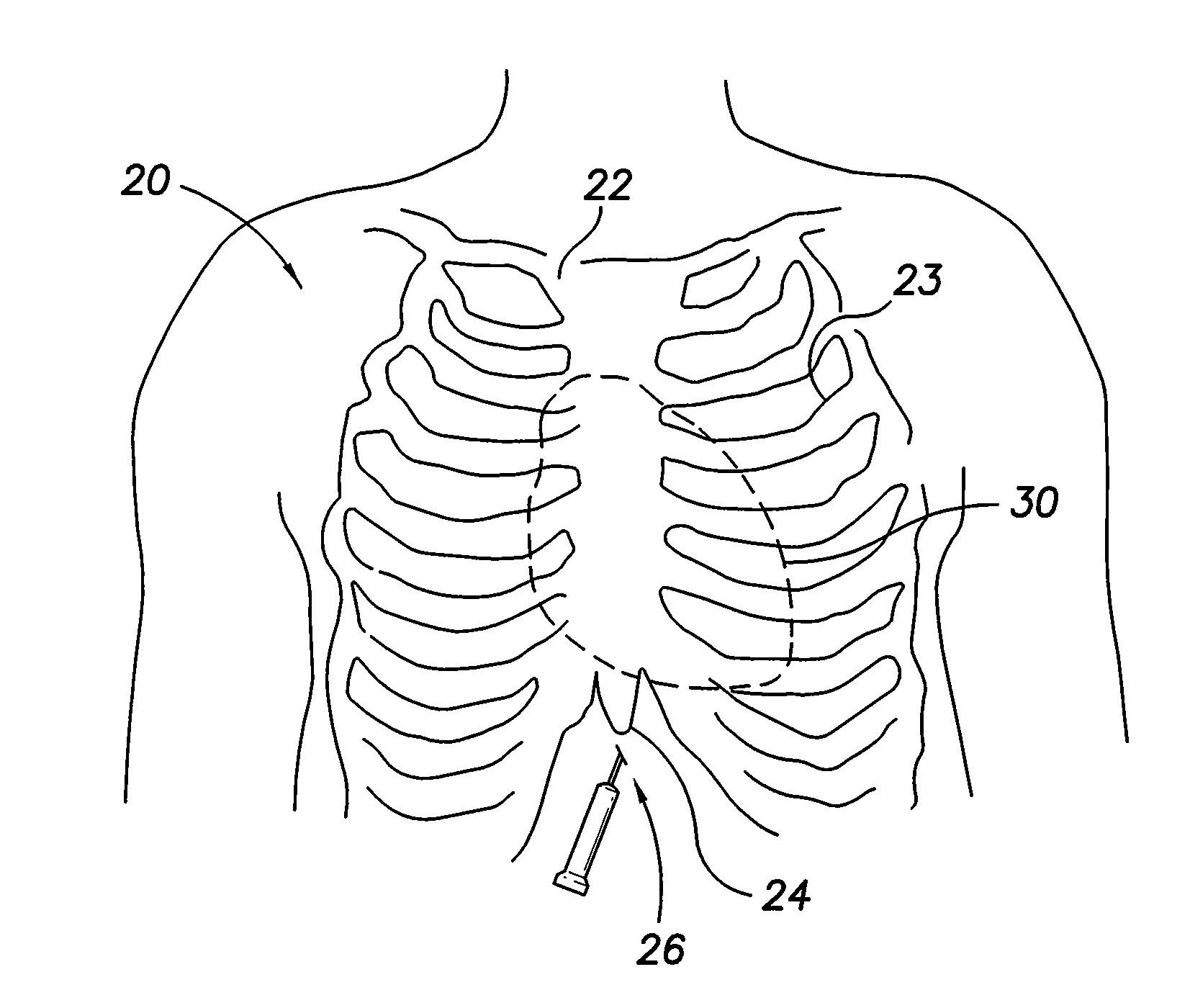
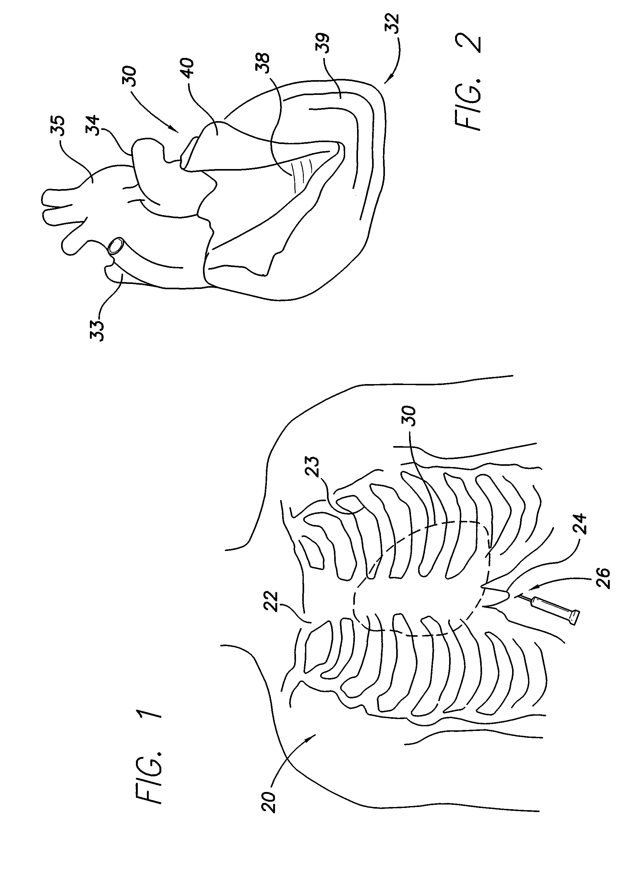
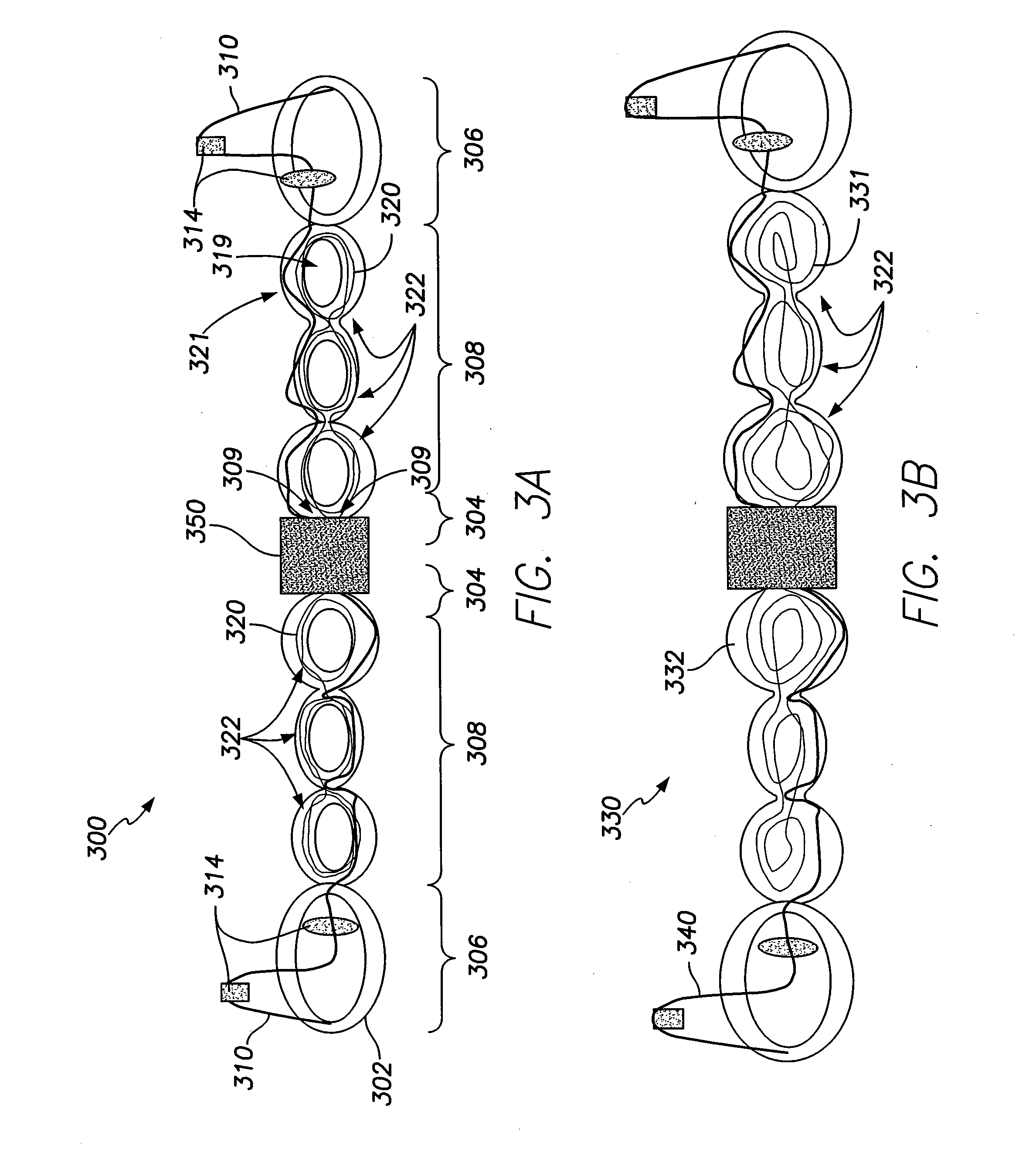
[0036]Embodiments of the present invention provide an intra-pericardial medical device (IPMD) having, among other things, a unique telemetry design that is integrated into a lead body with pacing / sensing leads. The IPMD may be stretched to desired locations, such as LA and LV or traditional RA and RV or other combinations of the four heart chambers (RA, LA, and RV and LV). A small pacemaker unit (e.g. nano-pacer) may be located at an intermediate position (e.g. the center) along the lead body of the IPMD. The pacemaker unit may be positioned at an intermediate position with a telemetry antenna or, alternatively, at other locations such as at ends or a center point along the telemetry antenna and / or lead body.

[0037]Embodiments disclosed herein are directed to IPMDs that facilitate and enhance the accurate placement (and monitoring of such placement) of medical electrodes. Although embodiments may be used in a variety of medical procedures, they are suited for installation as a cardia...


PUM

PropertyMeasurementUnit
Thicknessaaaaaaaaaa
Flexibilityaaaaaaaaaa
Energyaaaaaaaaaa

Abstract

An intra-pericardial medical device is provided that comprises a lead body having a proximal portion, a distal end portion, and an intermediate portion extending between the proximal portion and the distal end portions. An intra-pericardial medical device further includes the control logic housed with the lead body and an energy source housed within the lead body. A stimulus conductor is included and extends along the lead body. An electrode is joined to the stimulus conduct near the distal end portion, where the electrode configured to deliver stimulus pulses. A telemetry conductor is provided within the lead and extends from the proximal portion and along the intermediate portion of the lead body. The telemetry conductor is wound into a series of coil groups to form inductive loops for at least one of receiving and transmitting radio frequency (RF) energy.

Description

BACKGROUND OF THE INVENTION[0001]Embodiments of the present invention generally relate to implantable cardiac devices, and more particularly to intra-pericardial medical devices having a built-in telemetry system.[0002]Implantable medical devices, for example, pacemakers, cardio-defibrillators, neurostimulators and the like, utilize leads to form the electrical connection between a device pulse generator and tissue or nerves that are to be stimulated. As is well known, the leads connecting such devices with the heart may be used for pacing or for sensing electrical signals produced by the heart, or for both pacing and sensing in which case a single lead serves as a bidirectional pulse transmission link between the device and the heart. The lead typically comprises a distal end portion for carrying a tip electrode and a ring electrode. The lead may also carry one or more cardioverting and / or defibrillation shocking electrodes.[0003]Various lead types for different placement approache...

Claims


Application Information

Patent Timeline
IPC IPC(8): A61N1/08H01Q17/00A61N1/36
CPCH01Q1/2225H01Q1/44A61N1/0587Y10T29/49018A61N1/37229A61N2001/086A61N1/3624A61N1/086
Inventor MIN, XIAOYI
Owner PACESETTER INC
Why Eureka
Try Eureka