Cooler arrangement for a vehicle powered by a supercharged combustion engine

a technology of supercharged combustion engines and cooling arrangements, which is applied in the direction of steam engine plants, machines/engines, mechanical equipment, etc., can solve the problems of low fuel consumption, and achieve the effect of reducing the temperature of the cooling arrangement and good thermal energy absorption

Inactive Publication Date: 2013-03-21
SCANIA CV AB
View PDF8 Cites 29 Cited by
  • Summary
  • Abstract
  • Description
  • Claims
  • Application Information

AI Technical Summary

Benefits of technology

[0008]According to an embodiment of the present invention, the energy recovery system comprises two condensers and the coolant in the second cooling circuit is used to cool the medium in a first condenser and the coolant in the third cooling circuit is used to cool the medium in a second condenser which is situated downstream of the first condenser. The cooling of the medium is important for achieving good absorption of thermal energy in the heat recovery system. It may therefore be necessary to subject the medium to two steps of cooling in two separate condensers. In this case it is advantageous to use the coolant in the second cooling circuit to subject the medium to a first step of cooling and the coolant in the third cooling circuit to subject the medium to a second step of cooling. The energy-absorbing system comprises with advantage at least one heat exchanger in which the medium is intended to absorb thermal energy from a heat source in the form of warm coolant, compressed air, exhaust gases in the exhaust line or recirculating exhaust gases. All of these heat sources contain surplus heat which can be utilised in the energy recovery system. The coolant, the compressed air and the recirculating exhaust gases are normally cooled in at least one cooler to lower their temperature, in which case the heat exchanger may replace or complement such an ordinary cooler.
[0009]According to an embodiment of the present invention, the vehicle comprises a return line for recirculation of exhaust gases and the recirculating exhaust gases are cooled in an EGR cooler by coolant from the third cooling circuit or by the medium after it has been cooled by the coolant in the third cooling circuit in the condenser. In cases where exhaust gases are added to the compressed air which is led to the combustion engine, it is advantageous to cool the recirculating exhaust gases to the same low temperature as the compressed air. It is therefore appropriate to use the coolant in the third cooling circuit for this purpose. Alternatively, the medium may be used to similar effect after it has been cooled by the coolant in the third cooling circuit. The first cooling circuit contains with advantage coolant which is used for cooling the combustion engine. The operating temperature of this coolant should normally be about 70-90° C. to cool the combustion engine to a suitable temperature. The coolant in the first cooling circuit, the second cooling circuit and the third cooling circuit may of course be used to meet other cooling requirements in the vehicle. Since the coolant will be at different temperatures in the three cooling circuits, the coolant which is at the most suitable temperature may be used in each case.

Problems solved by technology

Such cooling makes it possible for a large amount of air to be led to the combustion engine, resulting in low fuel consumption.

Method used


Image

  • Cooler arrangement for a vehicle powered by a supercharged combustion engine
  • Cooler arrangement for a vehicle powered by a supercharged combustion engine
  • Cooler arrangement for a vehicle powered by a supercharged combustion engine

Examples


Embodiment Construction

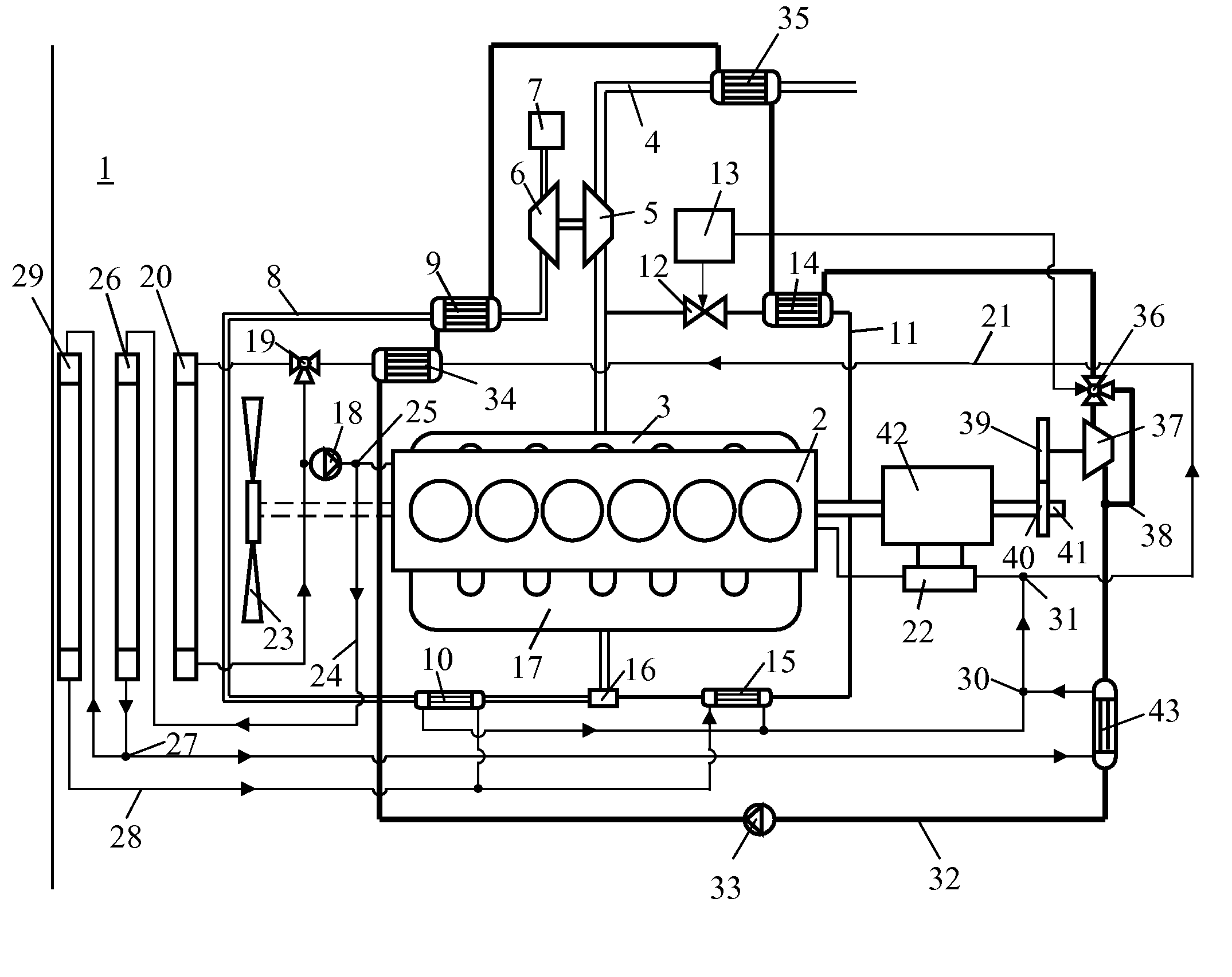
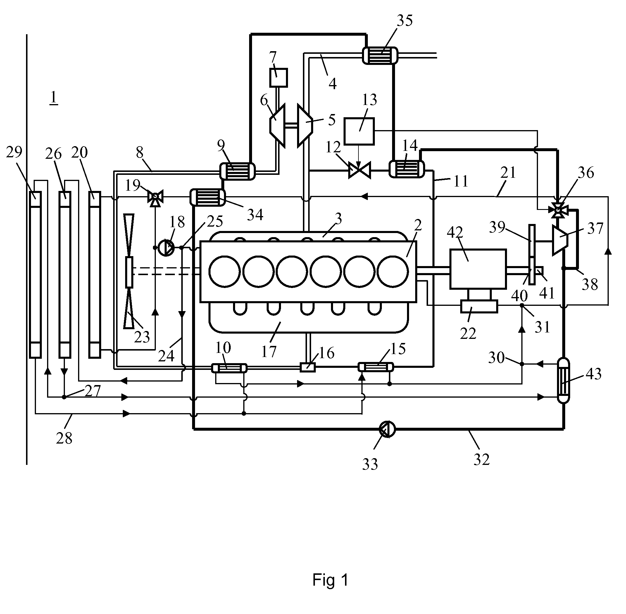
[0014]FIG. 1 depicts a supercharged combustion engine adapted to powering a schematically depicted vehicle 1 which may be a heavy vehicle 1. The combustion engine 2 is here exemplified as a diesel engine 2. The exhaust gases from the cylinders of the diesel engine 2 are led to an exhaust line 4 via an exhaust manifold 3. The diesel engine 2 is provided with a first turbo unit which comprises a turbine 5 and a compressor 6. The exhaust gases in the exhaust line 4 expand through the turbine 5, which is thus provided with driving power which is transmitted, via a connection, to the compressor 6. The arrangement comprises an inlet line 8 adapted to leading air to the combustion engine 2. The compressor 6 of the first turbo unit compresses air which is drawn into an inlet line 8 via an air filter 7. In the inlet line 8, the air undergoes a first step of cooling in a first charge air cooler 9 and a second step of cooling in a second charge air cooler 10.

[0015]The arrangement comprises a r...


PUM


Abstract

A cooler arrangement for a vehicle which is powered by a supercharged combustion engine. The vehicle has at least one charge air cooler (10) for cooling of compressed air which is led to the combustion engine (2), and an energy recovery system. The vehicle also has a cooler arrangement of a first cooling circuit with a first cooler (20) for cooling a circulating coolant, a second cooling circuit with a second cooler (26) for cooling a circulating coolant to a lower temperature than the first cooler (20), and a third cooling circuit with a third cooler (29) for cooling a circulating coolant to a lower temperature than the second cooler (26). The coolant in the third cooling circuit cools the compressed air in the charge air cooler (10) and/or a medium in a condenser (45) in a cooling medium line (32).

Description

BACKGROUND TO THE INVENTION AND PRIOR ART[0001]The present invention relates to a cooler arrangement for a vehicle which is powered by a supercharged combustion engine according to the preamble of claim 1.[0002]The development of the performance of combustion engines and the requirement for ever lower emissions in their exhaust gases have resulted in ever increasing cooling requirements in vehicles. The air which is led to a combustion engine is compressed to high pressure before it is led to the engine. Compressing the air causes it to acquire a raised temperature which is related to the degree of compression. To reduce the volume of the compressed air, it is cooled in one or more charge air coolers before it is led to the engine. The technique called EGR (exhaust gas recirculation) is a known way of leading back part of the exhaust gases of a combustion engine. Adding exhaust gases to the air causes a lower combustion temperature resulting inter alia in a reduced content of nitrog...

Claims


Application Information

Patent Timeline
Patent Type & Authority Applications(United States)
IPC IPC(8): F02B29/04
CPCF01P3/20F01P7/165F01P2003/187F01P2060/16F02B29/04F02G5/04F02G2260/00Y02T10/146Y02T10/166F02B29/0412F01P2060/02Y02T10/12F01P7/14
Inventor KARDOS, ZOLTANKLINGBERG, KRISTOFFER
Owner SCANIA CV AB
Why Eureka
Try Eureka