
Insulated concrete form and method of using same

a technology of concrete and insulating parts, applied in the direction of auxillary members of forms/shuttering/falseworks, building repairs, manufacturing tools, etc., to achieve the effect of improving the curing environment and easy and inexpensive attachmen

Inactive Publication Date: 2013-03-28
CIUPERCA ROMEO ILARIAN
View PDF45 Cites 94 Cited by
  • Summary
  • Abstract
  • Description
  • Claims
  • Application Information

AI Technical Summary

Benefits of technology

The invention is about an insulated concrete system that has improved sound insulation and a better curing environment for concrete. This results in a better performing and more durable mission-critical structure.

Problems solved by technology

The exposure of the concrete to the elements, especially temperature variations, makes the curing of the concrete, and the ultimate strength it can achieve, as unpredictable as the weather.
Therefore concrete structures are typically overdesigned with significant safety factors to make up for the unknown variables and uncertainty of the curing process.
Thus, although they have many advantages, concrete buildings have relatively poor energy efficiency.
While insulated concrete forms of the prior art provide relatively high energy efficiency, they lack the strength to withstand the relatively high fluid concrete pressures experienced by conventional concrete forms.
Consequently, they are relegated mostly to residential construction or low-rise construction and find few applications in commercial construction.
However all types of foam have relatively low strength and structural properties.
Therefore, insulated concrete forms of the prior art are relatively weak and cannot withstand the same high pressures experienced by conventional forms.
First, in the construction of an exterior wall of a building, multiple insulated concrete form modules are stacked upon and placed adjacent to each other in order to construct the concrete form. In some insulated concrete form systems, the form spacers / interconnectors are placed in the joints between adjacent concrete form modules. Such form systems are not strong enough to build a form more than a few feet high. Concrete is then placed in the form and allowed to harden sufficiently before another course of insulating forms are added on top of the existing forms. Such systems result in cold joints between the various concrete layers necessary to form a floor-to-ceiling wall or a multi-story building. Cold joints in a concrete wall weaken the wall therefore requiring that the wall be thicker and / or use higher strength concrete than would otherwise be necessary with a wall that did not have cold joints. This generally limits current use of insulated concrete forms to buildings of a single story or two in height or to infill wall applications.
Second, the use of multiple form modules to form a wall, or other building structure, creates numerous joints between adjacent concrete form modules; i.e., between both horizontally adjacent form modules and vertically adjacent form modules. Such joints provide numerous opportunities for water from the concrete mix to leak out of the form. The proper amount of water and heat is necessary for concrete to harden to its maximum potential strength. Thus, the loss of water through leaky joints in adjacent form modules reduces the strength of the concrete.
Third, the use of multiple form modules to form a wall, or other building structure, creates numerous joints between adjacent concrete form modules; i.e., between both horizontally adjacent form modules and vertically adjacent form modules. The sum of all these joints makes the prior art insulated concrete forms inherently unstable and concrete blowouts are not uncommon. Since the wall forms are unstable, the use of additional forming materials, such as plywood, to stabilize the modular insulated concrete forms is required before concrete is poured. These additional materials are costly and time consuming to install. The multiple joints also provide numerous opportunities for water to seep into and through the concrete wall. Furthermore, some of the prior art wall spacer systems create holes in the insulated concrete forms through which water can seep, either in or out. Thus, the prior art modular insulated concrete forms do little, or nothing, to prevent water intrusion in the finished concrete wall.
Fourth, prior art modular insulated concrete form systems are difficult and time consuming to put together, particularly at a constructions site using unskilled labor.
Fifth, prior art modular insulated concrete form systems do little, or nothing, to produce a stronger concrete wall.
Sixth, prior art modular insulated concrete form systems do not meet the high pressure ratings that conventional concrete forms do.
Seventh, prior art modular insulated concrete form systems are designed to form walls and are not suitable for forming columns or piers or elevated concrete slabs.
Eighth, prior art modular insulated concrete form systems do not allow for forming of structural, load bearing high-rise construction
Ninth, prior art modular insulated concrete form systems only allow for one type of wall cladding to be applied, such as a directly applied finish system.
To install all other wall claddings, additional systems have to be installed, sometimes at greater expense than even in the conventional concrete forming systems.
Some prior art modular insulated concrete form systems do not allow for the use of other types of wall cladding systems.

Method used


Image

  • Insulated concrete form and method of using same
  • Insulated concrete form and method of using same
  • Insulated concrete form and method of using same

Examples


Embodiment Construction

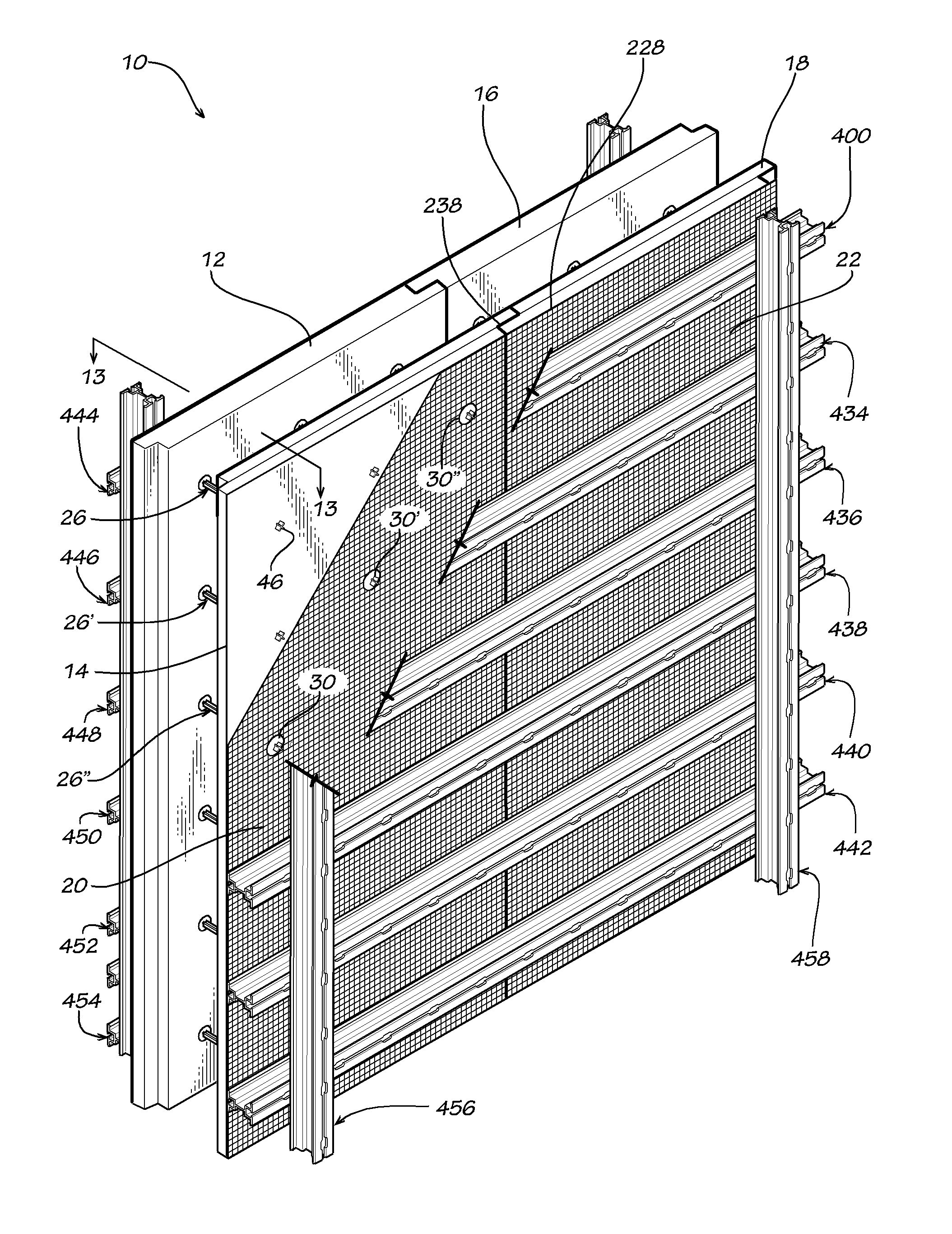
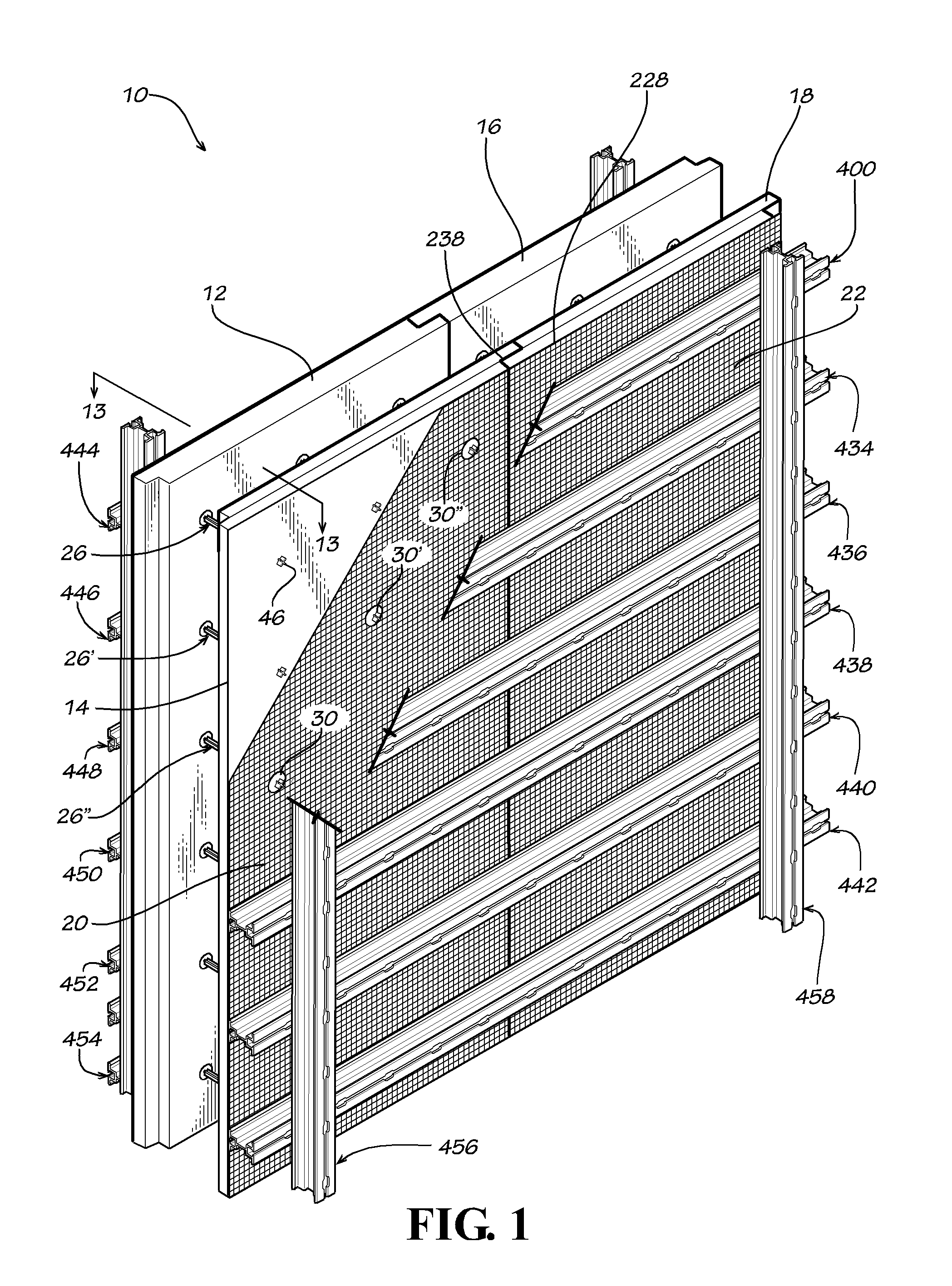
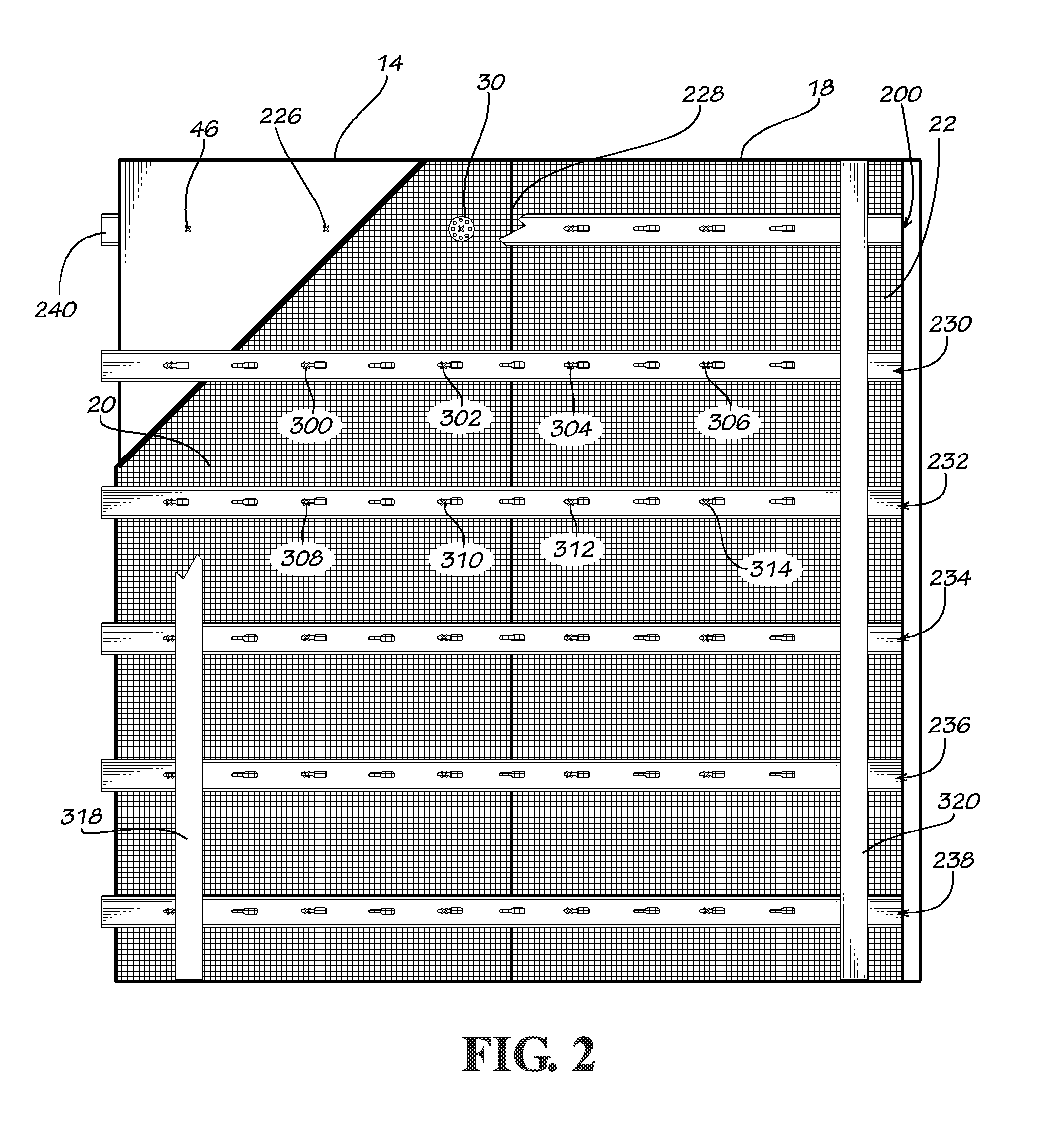
[0101]Referring now to the drawing in which like numbers indicate like elements throughout the several views, there is shown in FIG. 1 a disclosed embodiment of an insulated concrete form 10 in accordance with the present invention. The insulated concrete form 10 includes a first exterior foam insulating panel 12 generally parallel to and spaced apart from a first interior foam insulating panel 14. Adjacent the first exterior foam insulating panel 12 is a second exterior foam insulating panel 16; adjacent the first interior foam insulating panel 14 is a second interior foam insulating panel 18. The foam insulating panels 12-18 can be made from any insulating material that is sufficiently rigid to withstand the pressures of the concrete placed in the form. The foam insulating panels 12-18 are preferably made from a polymeric foam material, such as molded expanded polystyrene or extruded expanded polystyrene. Other polymeric foams can also be used including, but nor limited to, polyis...


PUM

PropertyMeasurementUnit
Diameteraaaaaaaaaa
Electrical resistanceaaaaaaaaaa
Heightaaaaaaaaaa

Abstract

The invention comprises connector for a pair of opposed spaced concrete forming panels. The connector comprises an elongate spacer member having flanges formed thereon intermediate a central portion thereof and each opposite end thereof. A portion of at least one end of the spacer member is sized and shaped to selectively engage an elongate panel bracing member. A composite insulated concrete form and a method of using the insulated concrete form are also disclosed.

Description

FIELD OF THE INVENTION[0001]The present invention generally relates to insulated concrete forms. More particularly, this invention relates to an insulated concrete form that is stronger than conventional insulated concrete forms so that it can hold the weight of a full lift of concrete and extend from floor to ceiling. The present invention also relates to an insulated concrete form that is easier to assemble and easier to use. The present invention also relates to an insulated concrete form that results in stronger concrete cured therein. The present invention also relates to an insulated concrete form that produces a wall that resists or prevents water intrusion. The present invention also related to an insulated concrete form for elevated slabs and roof systems. The present invention also relates to methods of using the insulated concrete form of the present invention. The present invention also related to a concrete structure that has a longer useful life than conventional concr...

Claims


Application Information

Patent Timeline
IPC IPC(8): E04B2/40B23P11/00E04C2/20E04B1/38E04B1/21
CPCE04B1/21Y10T29/49632E04B2/40E04C2/20E04B1/161E04B1/4178E04B2/8647E04B2002/8688E04B5/38E04B9/245E04C5/168E04C5/18E04C5/20E04G11/06E04F13/0803E04F13/0832E04B1/38E04G17/0754E04G11/12E04G11/48E04G17/0654E04G17/0658E04G17/14
Inventor CIUPERCA, ROMEO ILARIAN
Owner CIUPERCA ROMEO ILARIAN
Learn More