Switchable radiator bypass valve set point to improve energy efficiency

a technology of bypass valve and switchable radiator, which is applied in the direction of mechanical equipment, machines/engines, transportation and packaging, etc., can solve the problems of reducing vehicular energy efficiency and typically consuming energy of cooling heaters, and achieve the effect of facilitating optimum energy efficiency and/or performance of the propulsion system, reducing excess heat, and reducing energy consumption

Active Publication Date: 2011-02-15
FORD GLOBAL TECH LLC
View PDF15 Cites 18 Cited by
  • Summary
  • Abstract
  • Description
  • Claims
  • Application Information

AI Technical Summary

Benefits of technology

[0009]In the absence of a heating event, the coolant system is normally operated according to the valve set point temperature. Therefore, the valve distributes the coolant through the radiator as needed, which dissipates excess heat from the coolant to subsequently facilitate absorption of heat by the coolant from the propulsion system to facilitate optimum energy efficiency and / or performance of the propulsion system. During a heating situation, the coolant heater is operated to heat the coolant prior to distribution of the coolant into the heater core. Accordingly, at the onset of the heating situation, the valve set point temperature is elevated to substantially match the heater set point temperature. Therefore, the valve shunts the coolant through the radiator bypass line such that heat is retained in the coolant. Consequently, the coolant heater consumes less vehicle energy than would have been the case had the elevation of the valve set point not occurred since the temperature of the coolant subsequently flowing into the coolant heater is now substantially the same as the heater set point temperature. When the heating situation no longer exists, the valve set point temperature returns to the original value to facilitate optimal energy efficiency and / or performance of the propulsion system efficiency.

Problems solved by technology

Under certain operating conditions, there may be situations, which call for additional temperature requirements at another point in the cooling system.
In heating situations, the coolant heater typically consumes energy in order to heat the coolant.
This can lead to reduced vehicular energy efficiency because the coolant heater is consuming energy to add heat to the coolant while the valve is distributing the coolant through the radiator in order to draw the heat back out of the coolant.

Method used


Image

  • Switchable radiator bypass valve set point to improve energy efficiency
  • Switchable radiator bypass valve set point to improve energy efficiency

Examples


Embodiment Construction

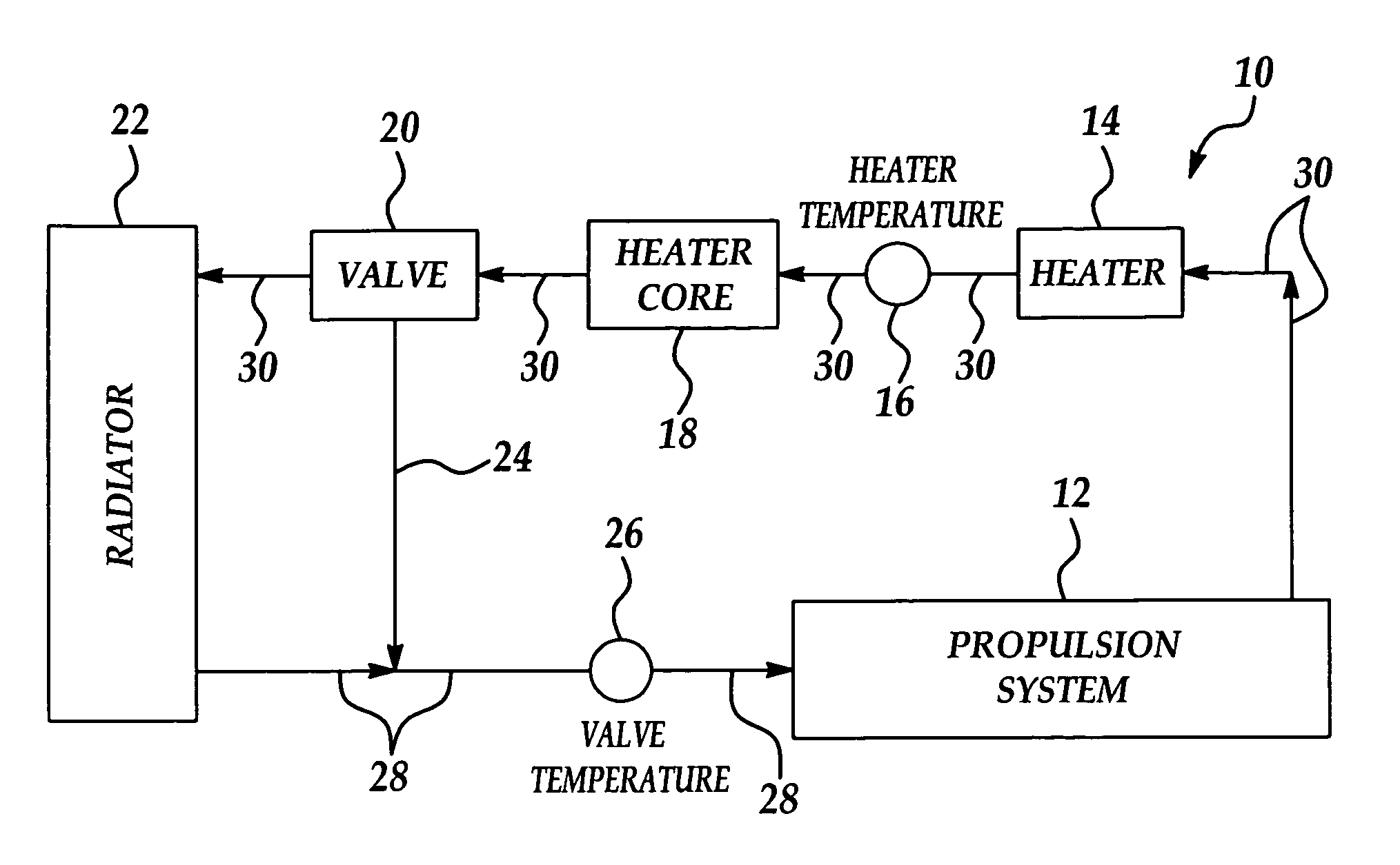
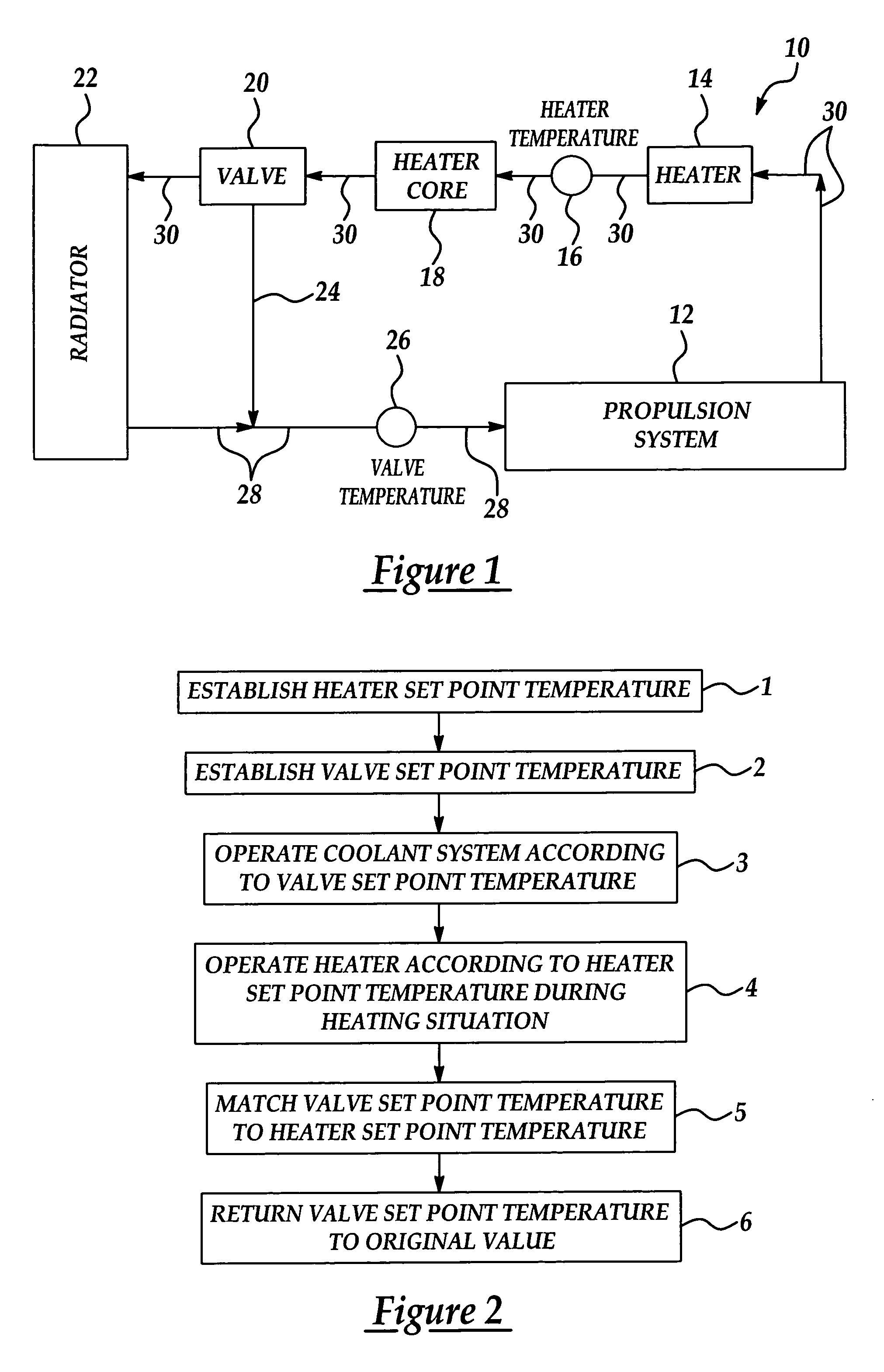
[0013]Referring initially to FIG. 1, a schematic diagram of a coolant system in implementation of the present invention is generally indicated by reference numeral 10. The coolant system 10 may be a vehicle coolant system, which is designed to absorb heat from a propulsion system 12, such as an internal combustion engine or a fuel cell stack, for example, which propels a vehicle. The propulsion system 12 is disposed in fluid communication with a coolant inlet line 28, which distributes a liquid coolant into the propulsion system 12, and a coolant outlet line 30, which distributes the coolant from the propulsion system 12. As used herein, the term “downstream” refers to the direction of coolant flow through the coolant inlet line 28 or coolant outlet line 30 of the vehicle coolant system 10.

[0014]A coolant heater 14 is typically provided in the coolant outlet line 30, downstream of the propulsion system 12. A heater core 18 is provided in the coolant outlet line 30, downstream of the...


PUM


Abstract

A method of conserving energy during a heating event wherein a coolant is heated in a cooling system is disclosed. The method includes establishing a first set point temperature for a first point in the cooling system and establishing a second set point temperature lower than the first set point temperature for a second point in the cooling system. Normally, the coolant is maintained at the second set point temperature at the second set point in the cooling system. During the heating event, the second set point temperature is raised to substantially match the first set point temperature to reduce necessary heating of the coolant at the first point.

Description

CROSS-REFERENCE TO RELATED APPLICATIONS[0001]This application claims the benefit of U.S. Provisional Application No. 60 / 622,650, filed Oct. 27, 2004.FIELD OF THE INVENTION[0002]The present invention relates to coolant systems for vehicles. More particularly, the present invention relates to a coolant temperature control method which utilizes matching of a valve temperature set point, which controls the temperature of a coolant flowing into a propulsion system, and a heater set point, which controls the temperature of a coolant flowing into a heater core, in heating situations and reversion of the valve temperature set point back to a value which is optimal for efficient operation of the propulsion system in non-heating situations.BACKGROUND OF THE INVENTION[0003]In an automotive cooling system, an electronically controlled valve or other flow control device may control the temperature of a coolant at one point in the system, such as at the entry point of the coolant into the propuls...

Claims


Application Information

Patent Timeline
Patent Type & Authority Patents(United States)
IPC IPC(8): F24J3/00F01P7/16
CPCF01P7/167F01P2025/50F01P2037/02F01P2060/08F01P2060/18B60H1/03B60K11/02F01P7/165
Inventor SCHWARTZ, WILLIAMHUANG, CHENDONGFAN, STEPHENPATEL, UPENDRAJACKSON, KENSTANEK, JOSEPH
Owner FORD GLOBAL TECH LLC
Why Eureka
Try Eureka