Electric working vehicle

a technology of working vehicle and resistor, which is applied in the direction of propulsion using engine-driven generators, electric propulsion mounting, transportation and packaging, etc., can solve the problems of resistor wetness with rain water, deterioration of insulation properties between resistor and vehicle body frame circuit, and possible earth fault of short circuit with respect to ground. , to achieve the effect of enhancing the insulation properties of the resistor

Inactive Publication Date: 2013-03-28
NIHON KENKI CO LTD
View PDF17 Cites 11 Cited by
  • Summary
  • Abstract
  • Description
  • Claims
  • Application Information

AI Technical Summary

Benefits of technology

[0005]Meanwhile, in the electric working vehicle according to the above-described conventional art, the resistor may be frozen up in cold climates and, on the other hand, the resistor may get wet with rain water at the time of rainfall. In this case, insulation properties between a circuit for the resistor and a vehicle body frame are deteriorated, and a so-called earth fault that the circuit is short-circuited with respect to the ground may possibly occur. As a function that avoids this earth fault trouble, a configuration that carries out heat generation using the resistor and air blow using a blower at the same time can be considered. According to this configuration, pieces of ice can be molten or moisture can be evaporated by the heat generation of the resistor, and the resistor can be dried by the air blow from the blower, thereby eliminating factors that deteriorate the insulation properties.
[0007]In view of the above-described problem with the conventional art, it is an object of the present invention to provide an electric working vehicle that can arbitrarily select heat generation using a resistor and air blow using a blower in accordance with a state of the resistor, a condition of outside air, and the like.
[0009]With this arrangement, an operator can select an appropriate mode from the three modes that can be selected using the mode selecting switch in accordance with a state of the resistor, a condition of outside air, and the like. Specifically, for example, the heating mode for performing the heat generation alone can be selected in case of a snowstorm or heavy rains, whereby moisture in the periphery can be evaporated by the heat generation of the resistor while avoiding the blowing-in of the snowstorm and the like. On the other hand, when water is stored around the resistor, the blowing mode for performing air blow alone can be selected to blow off the stored water. Furthermore, when the resistor is frozen up, the heating and blowing mode for simultaneously performing the heat generation and the air blow can be selected to dry the resistor while melting ice of the resistor. As described above, a mode in accordance with a state of the resistor or outside air can be selected to enhance the insulation properties of the resistor, and the regenerative power of the electric motor can be assuredly consumed by the resistor.
[0013]With this arrangement, the controller can stop the heat generation using the resistor and the air blow using the blower to eliminate extra power consumption at the time of acceleration of the vehicle body. Since the direct current power is converted into the alternating current power by the bidirectional converter to be supplied to the electric motor in this state, the direct current power from the direct current power supply can be supplied to the electric motor without being consumed by the resistor.
[0017]This configuration comprises the mode change processing device that changes the current mode to the blowing mode when an increase in temperature of the resistor is not detected by the temperature sensor with the heating mode being selected. Here, when a temperature of the resistor is not increased in the heating mode, it can be considered that selection of the heating mode is inappropriate like a situation that the insulation properties of the resistor are greatly deteriorated, for example. In such a case, since the heating mode switching device can change the current mode to the blowing mode in which air blow using the blower is performed, the water stored around the resistor can be blown off to enhance the insulation properties of the resistor. As a result, the inappropriate heating mode can be automatically changed to the blowing mode, and an appropriate operation can be carried out to keep a machine stop time to the minimum.
[0019]This configuration comprises the mode change processing device that changes the current mode to the heating mode when a pressure difference detected by the differential pressure sensor is smaller than the minimum pressure difference with the blowing mode being selected. Here, when a pressure difference between a pressure of the resistor on the upstream side and that on the downstream side in the blowing mode is smaller than the minimum pressure difference, it can be considered that selection of the blowing mode is inappropriate like a situation where the blower has failed to operate properly, for example. In such a case, since the blowing mode switching device can change the current mode to the heating mode for performing the heat generation using the resistor, moisture can be evaporated by the heat generation of the resistor, thus enhancing insulation properties of the resistor. As a result, the inappropriate blowing mode can be automatically changed to the heating mode, and an appropriate operation can be carried out to keep the machine stop time to the minimum.

Problems solved by technology

Meanwhile, in the electric working vehicle according to the above-described conventional art, the resistor may be frozen up in cold climates and, on the other hand, the resistor may get wet with rain water at the time of rainfall.
In this case, insulation properties between a circuit for the resistor and a vehicle body frame are deteriorated, and a so-called earth fault that the circuit is short-circuited with respect to the ground may possibly occur.
However, simultaneously performing the heat generation and the air blow may be inappropriate depending on a state of the resistor, a condition of outside air, and the like.
For example, when water is stored around the resistor to considerably deteriorate the insulation properties, the resistor cannot sufficiently generate heat.
In this case, even if power is fed to the resistor, an amount of leaking power is large, and a problem of poor energy efficiency arises.
On the other hand, when operating the blower in a snowstorm or heavy rains, snow and ice or rain water may be possibly drawn into the periphery of the resistor due to the effect of the air blow, and the insulation properties of the resistor may be further deteriorated.

Method used


Image

  • Electric working vehicle
  • Electric working vehicle
  • Electric working vehicle

Examples


first embodiment

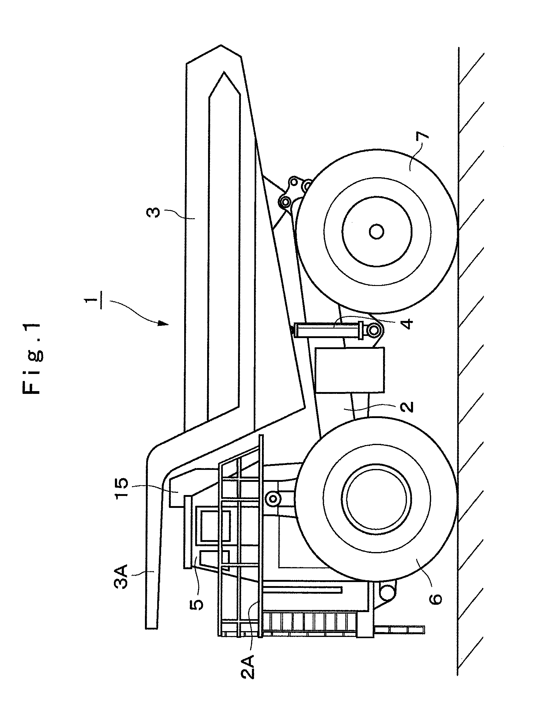
[0031]FIG. 1 to FIG. 6 show an electric working vehicle according to the present invention.

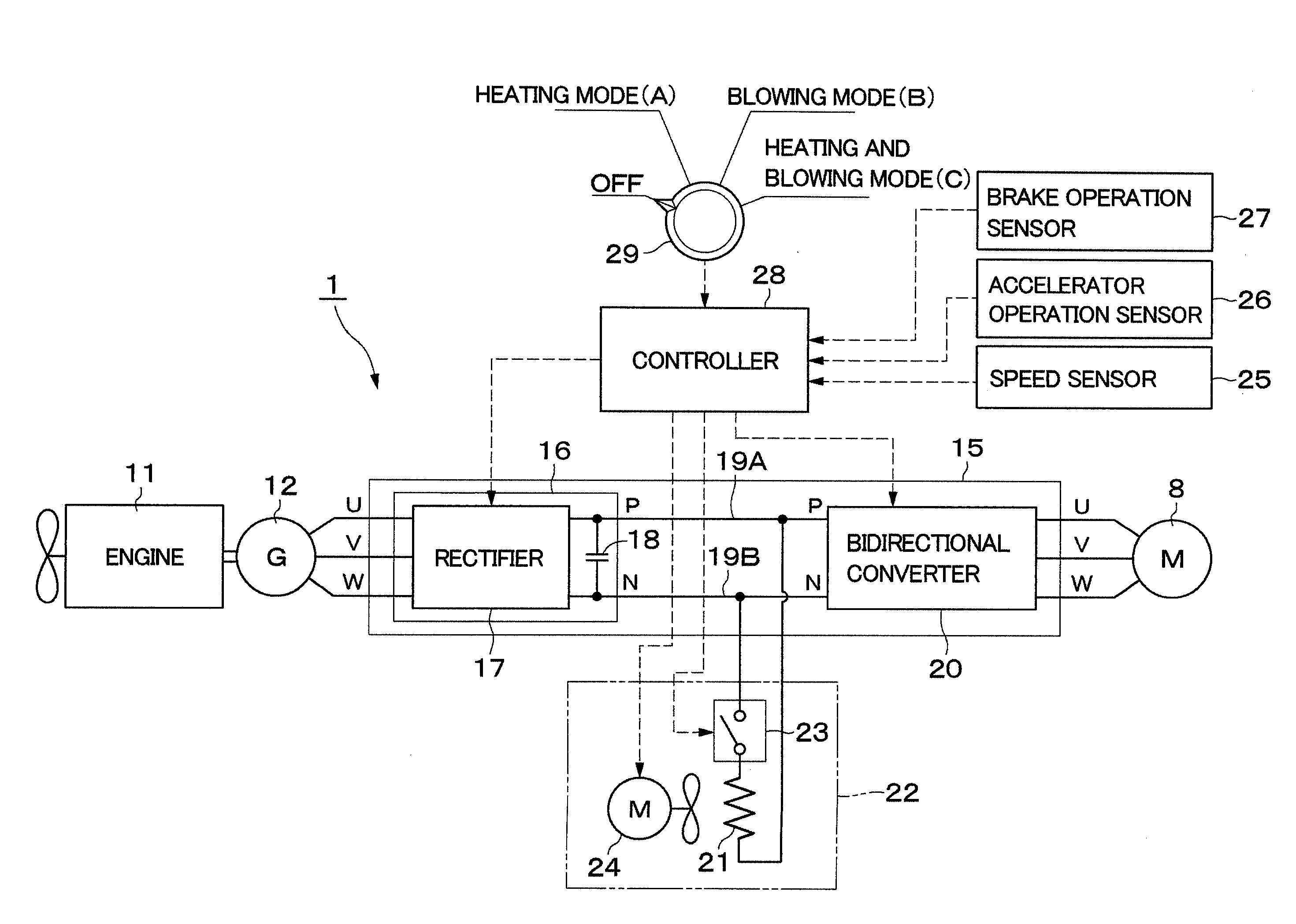
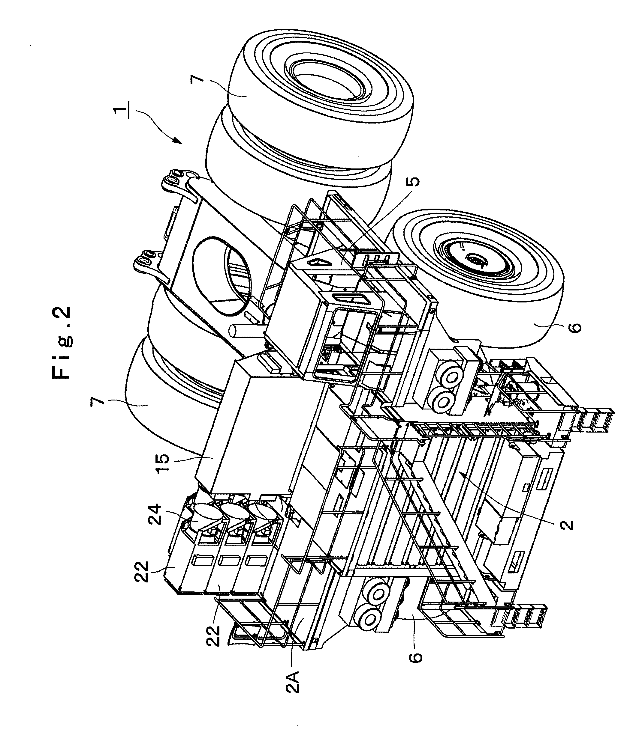
[0032]In the drawings, designated at 1 is a dump truck as the electric working vehicle. As shown in FIG. 1 and FIG. 2, the dump truck 1 has a robust frame structure and is largely constituted of a vehicle body 2 that is self-propelled with front wheels 6 and rear wheels 7 as below-described wheels and a vessel 3 as a loading platform mounted on the vehicle body 2 so as to be liftable with a rear end side being used as a fulcrum. The vessel 3 has a protector 3A that substantially completely covers a cabin 5 from above and performs lifting motion (tilt) by using hoist cylinders 4 arranged on both left and right sides of the vehicle body 2.

[0033]Indicated at 5 is the cabin that is placed below the protector 3A and provided in a front portion of the vehicle body 2. This cabin 5 is placed on, for example, the left side of the vehicle body 2 and arranged on a deck portion 2A serving as a flat floor ...

second embodiment

[0074]Next, FIG. 7 and FIG. 8 show a second embodiment according to the present invention. The second embodiment is characterized in that a controller automatically changes a heating mode to a blowing mode when the heating mode is selected and a temperature sensor does not detect an increase in temperature of a resistor. In the second embodiment, the component elements that are identical to those of the foregoing first embodiment will be simply denoted by the same reference numerals to avoid repetitions of similar explanations.

[0075]Designated at 31 is a dump truck according to the second embodiment. This dump truck 31 includes wheel drive motors 8, an engine 11, a main power generator 12, an electric power control unit 15, a resistor 21, a switch 23, a blower 24, a mode selecting switch 29, and the like substantially similar to the dump truck 1 according to the first embodiment.

[0076]Denoted at 32 is a temperature sensor provided around the resistor 21. This temperature sensor 32 d...

third embodiment

[0084]Next, FIG. 9 and FIG. 10 show a third embodiment according to the present invention. The third embodiment is characterized in that a controller automatically changes a blowing mode to a heating mode when a pressure difference detected by a differential pressure sensor is smaller than a minimum pressure difference when the blowing mode is selected. In the third embodiment, the component elements that are identical to those of the foregoing first embodiment will be simply denoted by the same reference numerals to avoid repetitions of similar explanations.

[0085]Designated at 41 is a dump truck according to the third embodiment. This dump truck 41 includes wheel drive motors 8, an engine 11, a main power generator 12, an electric power control unit 15, a resistor 21, a switch 23, a blower 24, a mode selecting switch 29, and the like substantially similar to the dump truck 1 according to the first embodiment.

[0086]Denoted at 42 is a differential pressure sensor provided to a grid b...


PUM


Abstract

Wheel drive motors (8) constituted of electric motors for driving rear wheels (7) are provided on a vehicle body (2) of a dump truck (1). Each wheel drive motor (8) is connected to a main power generator (12) through a bidirectional converter (20) and the like and driven by power supplied from the main power generator (12). A resistor (21) that consumes regenerative power from each wheel drive motor (8) is connected to the bidirectional converter (20). Cooling air is supplied to the resistor (21) from a blower (24). Operations of a switch (23) of the resistor (21) and the blower (24) are controlled by a controller (28). A mode selecting switch (29) for selecting a heating mode (A), a blowing mode (B), and a heating and blowing mode (C) is connected to the controller (28).

Description

TECHNICAL FIELD[0001]The present invention relates to an electric working vehicle preferably used for a dump truck and the like, for example.BACKGROUND ART[0002]In general, there is known an electric working vehicle adopting an electric drive system for a traveling drive system like a large-sized dump truck and the like. Such an electric working vehicle is provided with an electric motor disposed to a vehicle body and an inverter provided between a direct current power supply such as a battery and the electric motor. On the other hand, there is known an electric working vehicle having a configuration that a resistor is connected to an inverter to consume electro motive force regenerated by an electric motor and a blower which supplies cooling air to the resistor is provided (Patent Document 1, Patent Document 2).PRIOR ART DOCUMENTSPatent Documents[0003]Patent Document 1: Japanese Patent Laid-Open No. 2006-230084 A[0004]Patent Document 2: Japanese Patent Laid-Open No. Hei 6-46505 ASU...

Claims


Application Information

Patent Timeline
Patent Type & Authority Applications(United States)
IPC IPC(8): B60K11/00B60K1/00B60L50/13
CPCB60L7/06B60L11/08B60L2200/40Y02T10/7077Y02T10/70B60K11/00Y10S903/902Y02T10/648B60K1/00B60L7/22B60L2250/00B60L50/13Y02T10/7072Y02T10/64
Inventor MINOSHIMA, TOSHIKAZUNAKAJIMA, KICHIO
Owner NIHON KENKI CO LTD
Why Eureka
Try Eureka