Ultraviolet Device Encapsulant

a technology of ultraviolet light and encapsulant, which is applied in the direction of transportation and packaging, synthetic resin layered products, coatings, etc., can solve the problems of increasing the stress on the material, uv leds continue to suffer from relatively low external quantum efficiency, and the typical epoxy resin materials used for visible led encapsulation are not adequate for uv leds

Active Publication Date: 2013-03-28
SENSOR ELECTRONICS TECH
View PDF4 Cites 27 Cited by
  • Summary
  • Abstract
  • Description
  • Claims
  • Application Information

AI Technical Summary

Benefits of technology

[0010]A third aspect of the invention provides a device package comprising: an ultraviolet device; and an encapsulant located adjacent to at least one surface of the ultraviolet device, wherein the encapsulant is a composite material including: a matrix material at least partially transparent to ultraviolet radiation of a target wavelength and having a matrix material thermal coefficient of expansion; a first filler material at least partially transparent to the ultraviolet radiation incorporated in the matrix material, wherein the first filler material includes at least one of: microparticles or nanoparticles and has a filler thermal coefficient of expansion significantly smaller than the matrix material thermal coefficient of expansion for relevant atmospheric conditions; and a second filler material including a plurality of fluorescent particles incorporated in the matrix material, wherein the plurality of fluorescent particles are visibly fluorescent under exposure to the ultraviolet radiation.
[0011]The illustrative aspects of the invention are designed to solve one or more of the problems herein described and / or one or more other problems not discussed.

Problems solved by technology

Despite tremendous efforts, UV LEDs continue to suffer from relatively low external quantum efficiencies.
Typical epoxy resin materials used for visible LED encapsulation are not adequate for UV LEDs as the resins are not sufficiently transparent to UV radiation and quickly deteriorate under the UV radiation.
During the curing process, drying of the encapsulant can further induce stresses in the material.

Method used


Image

  • Ultraviolet Device Encapsulant
  • Ultraviolet Device Encapsulant
  • Ultraviolet Device Encapsulant

Examples


Embodiment Construction

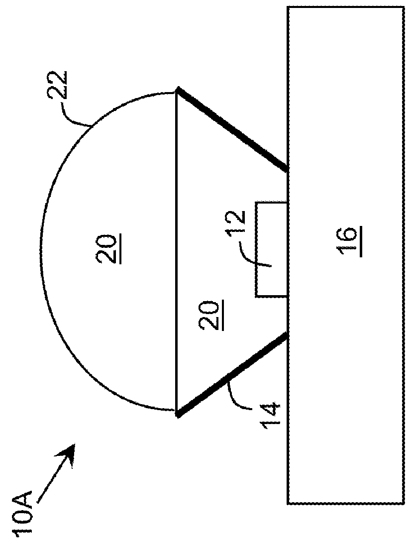
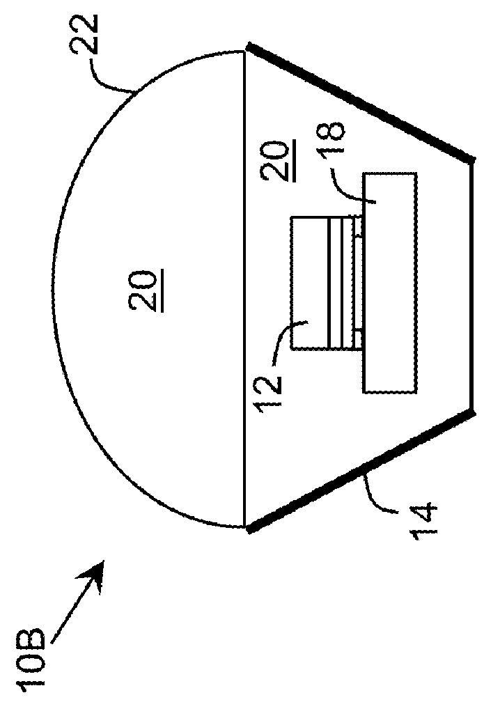
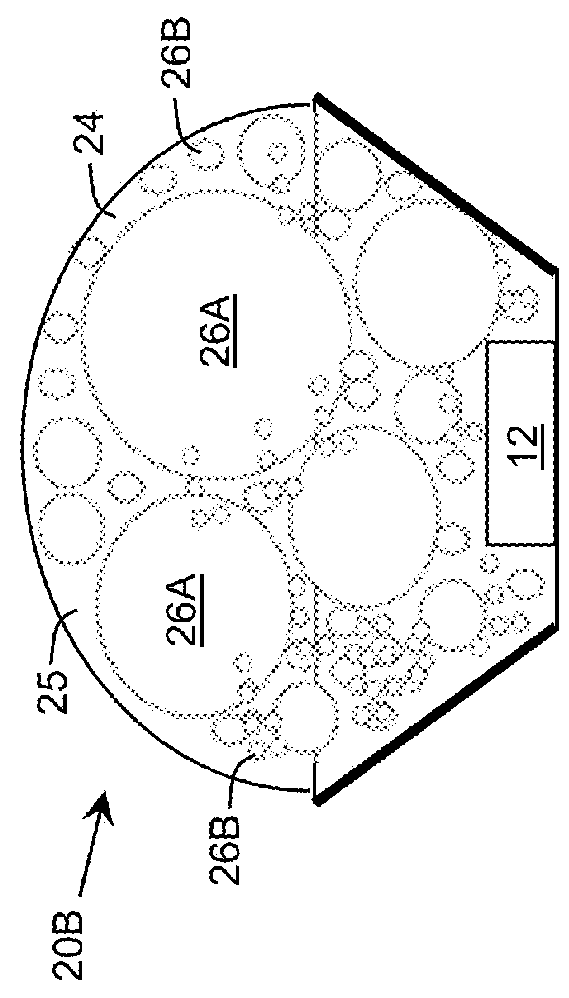
[0024]As indicated above, aspects of the invention provide a composite material, which can be used as an encapsulant for an ultraviolet device. The composite material includes a matrix material and at least one filler material incorporated in the matrix material that are both at least partially transparent to ultraviolet radiation of a target wavelength. The filler material includes microparticles and / or nanoparticles and can have a thermal coefficient of expansion significantly smaller than a thermal coefficient of expansion of the matrix material for relevant atmospheric conditions. The relevant atmospheric conditions can include a temperature and a pressure present during each of: a curing and a cool down process for fabrication of a device package including the composite material and normal operation of the ultraviolet device within the device package.

[0025]As used herein, a material is at least partially transparent when the material allows at least a portion of electromagnetic...


PUM

PropertyMeasurementUnit
thicknessaaaaaaaaaa
transparencyaaaaaaaaaa
thicknessaaaaaaaaaa

Abstract

A composite material, which can be used as an encapsulant for an ultraviolet device, is provided. The composite material includes a matrix material and at least one filler material incorporated in the matrix material that are both at least partially transparent to ultraviolet radiation of a target wavelength. The filler material includes microparticles and/or nanoparticles and can have a thermal coefficient of expansion significantly smaller than a thermal coefficient of expansion of the matrix material for relevant atmospheric conditions. The relevant atmospheric conditions can include a temperature and a pressure present during each of: a curing and a cool down process for fabrication of a device package including the composite material and normal operation of the ultraviolet device within the device package.

Description

REFERENCE TO RELATED APPLICATIONS[0001]The current application claims the benefit of co-pending U.S. Provisional Application No. 61 / 538,115, titled “Ultraviolet Light Emitting Diode Encapsulant,” which was filed on 22 Sep. 2011, and which is hereby incorporated by reference.GOVERNMENT LICENSE RIGHTS[0002]This invention was made with Federal government support under Contract No. W911NF-10-2-0023 awarded by Defense Advanced Research Projects Agency (DARPA). The government has certain rights in the invention.TECHNICAL FIELD[0003]The disclosure relates generally to ultraviolet light emitting devices, and more particularly, to an encapsulant for ultraviolet light emitting devices.BACKGROUND ART[0004]With recent advances in group III-based ultraviolet (UV) light emitting diode (LED) technology, interest in using UV LEDs for various applications, such as disinfection of medical tools, water purification, fluorescence spectroscopy, medical therapy, and the like, is increasing. Despite treme...

Claims


Application Information

Patent Timeline
Patent Type & Authority Applications(United States)
IPC IPC(8): B32B9/00C09K11/08C09D201/04C09D163/00C08K3/28C08K3/38C09D5/00B32B7/00C08K3/40B82Y30/00
CPCC09D163/00Y10T428/23H01L33/56C09K11/02C09K11/08
Inventor GASKA, REMIGIJUSSHATALOV, MAXIM S.DOBRINSKY, ALEXANDERYANG, JINWEISHUR, MICHAEL
Owner SENSOR ELECTRONICS TECH
Why Eureka
Try Eureka