Interface and Mud Control System and Method for Refinery Desalters

a technology of interface and mud control system and desalter, which is applied in the direction of sedimentation settling tank, separation process, instruments, etc., can solve the problems of high oil wet solids levels, upset water quality, and difficulty in coalescing fines, so as to promote a slow and continuous agitation of water

Active Publication Date: 2013-04-04
CAMERSON INT CORP
View PDF5 Cites 28 Cited by
  • Summary
  • Abstract
  • Description
  • Claims
  • Application Information

AI Technical Summary

Benefits of technology

[0010]Each nozzle in the plurality of nozzles lies in the same horizontal plane and is oriented toward an interior space of the desalter vessel at the same angular orientation as all other nozzles. Water flow through the nozzles, which may be in a range of 1 to 3 fpm, promotes a slow and continuous agitation of the water. The interface rag layer may be monitored and the water flow adjusted accordingly. Each nozzle may be a drilled passageway and is preferably oriented in the horizontal plane at an angle of about 15° to 60° relative to a pipe circuit center line and at a downward angle of about 15° to 60° from the horizontal plane. The rotation of the water, therefore, is coincident to the angular orientation of the nozzle in the horizontal plane, either clockwise or counterclockwise, and forms a toroidal rotation coincident to the downward angular orientation of the nozzles that gently sweeps both the bottom of the rag layer and the bottom of the vessel.

Problems solved by technology

Water droplets that are surrounded by these fines may be large enough to settle in the electrostatic desalter, but they are hindered from coalescing by the fines.
The disadvantage of periodic mud wash is that it sends high levels of oil wet solids to the water treatment facility where it must be handled for disposal.
These periodic injections of oil wet solids can initiate an upset in the water quality.
The disadvantage of both the semi-continuous and periodic methods is that solids are still allowed to settle in the bottom of the vessel where they can only be partially removed by each subsequent periodic washing.
While either method can handle the volume of fines in a refinery desalter, there remains a more significant problem that has not been properly dealt with before.
This problem is the solid-laden rag that hangs at the oil-water interface.
When the rate of collapse for interface rag is slower than the rate of accumulation, the interface volume increases and interferes with the desalter operation.
While the exact nature of this interface rag cannot be readily determined, the effects are detrimental to the performance of the desalter in one of two ways.
If the interface rag floats on top of the water, then it can grow in height until it interferes with the integrity of the electrostatic field by increasing the current demand and reducing the field strength.
The effect is a decline in the water quality that is passed to the water treatment facility as the interface rag settles to the bottom of the vessel to form mud and mixes with the brine exiting to the brine heat exchangers and benzene recovery unit.
Because refineries have more complex and overlapping issues, system applications need to be expanded beyond the simple purpose of removing sludge and solids from the bottom of desalter vessels.

Method used


Image

  • Interface and Mud Control System and Method for Refinery Desalters
  • Interface and Mud Control System and Method for Refinery Desalters
  • Interface and Mud Control System and Method for Refinery Desalters

Examples


Embodiment Construction

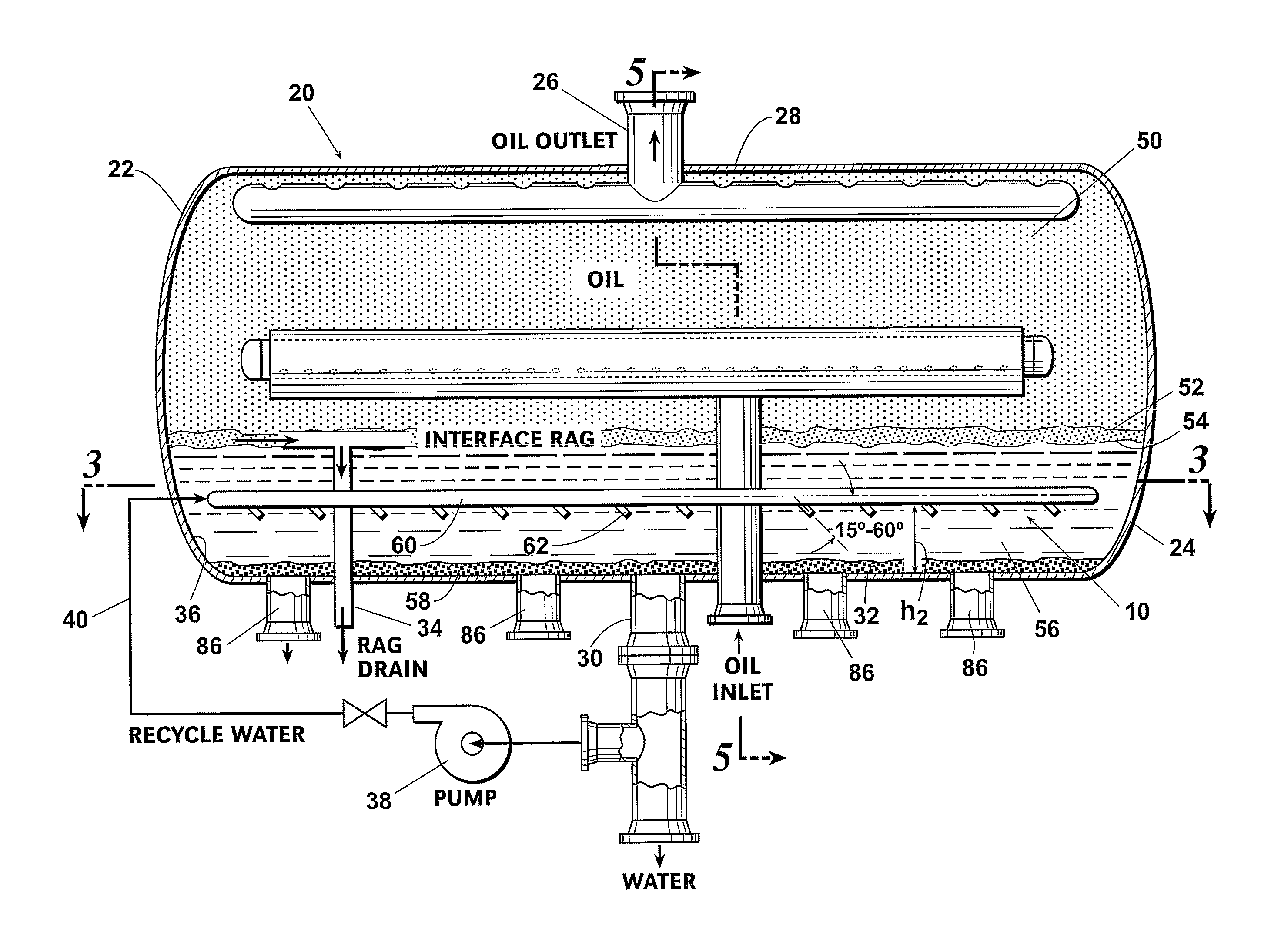
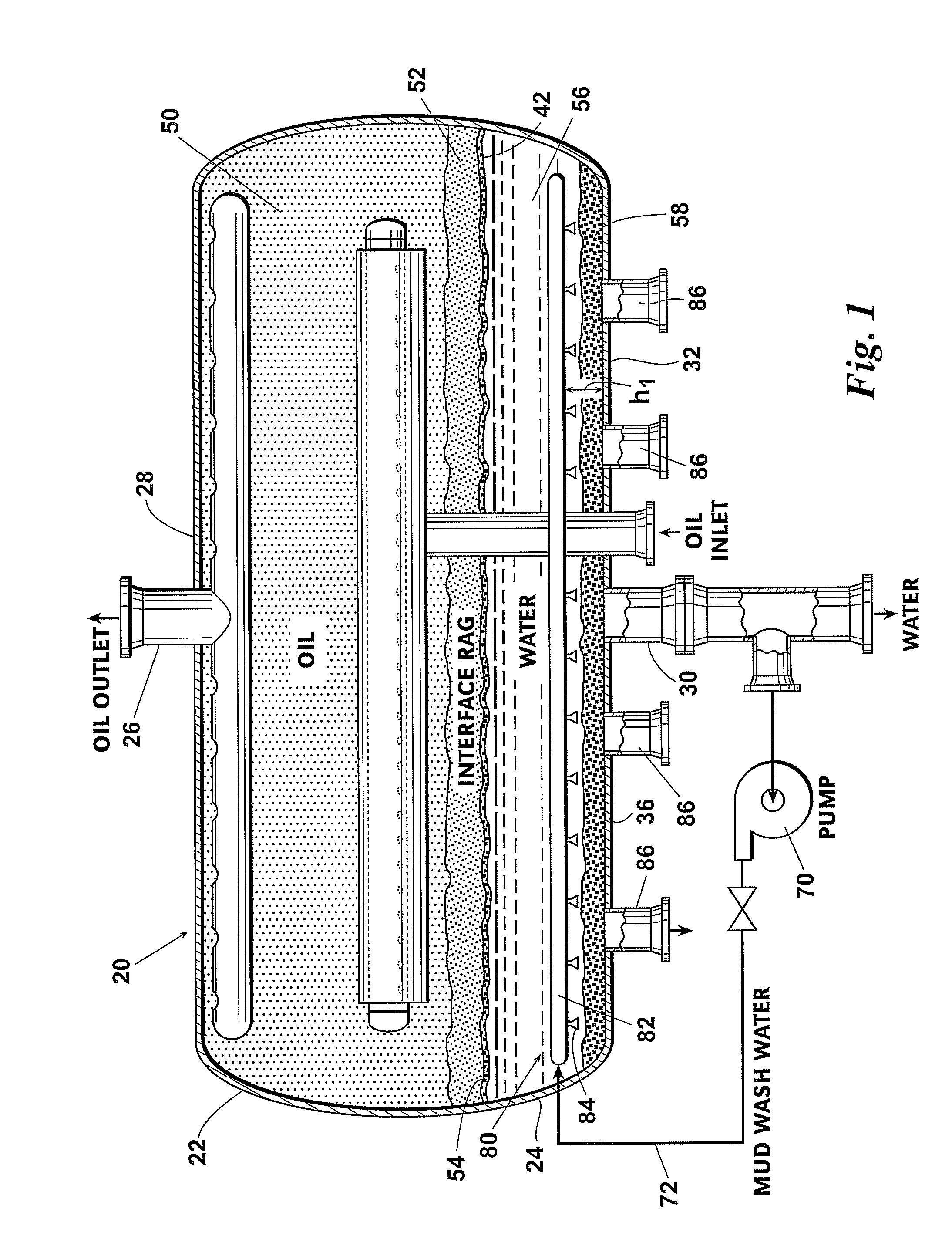
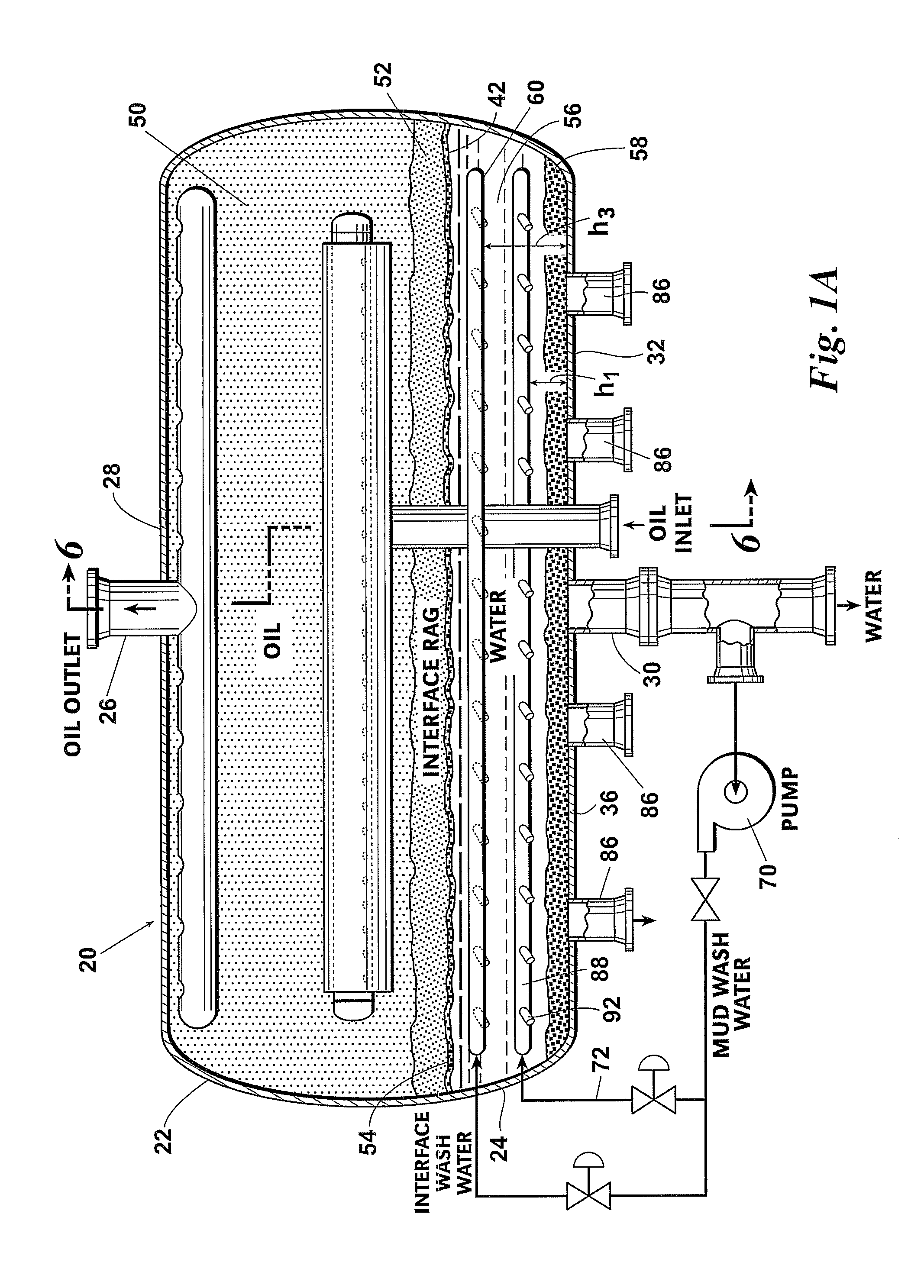
[0020]The present invention provides a method and system for preventing mud build-up within a separator vessel by continuously agitating the lower surface of the interface rag layer so as to suspend solids in the water layer and promote the collapse of mud residing in the interface rag layer. Elements illustrated in the drawings are identified by the following numbers:

10Interface emulsion control system20Separator vessel22Upper portion of 2024Lower portion of 2026Oil outlet28Top of 2030Water outlet32Bottom of 2034Rag drain36Inner wall surface of 2038Recycle pump40Recycle piping42Interface rag50Oil layer52Interface emulsion layer54Lower surface of 5256Water layer58Oil-coated solids / mud60First piping circuit62Nozzle64Outer periphery of 6066Inner periphery of 6068Centerline of 6070Recycle pump72Recycle piping80Mud wash system82Piping84Spray nozzle86Mud drain88Second piping circuit90Supports92Nozzle

[0021]Referring first to FIG. 1, a separator vessel 20 is connected by conventional pipin...


PUM

PropertyMeasurementUnit
angleaaaaaaaaaa
angleaaaaaaaaaa
oblique angleaaaaaaaaaa

Abstract

A method and system for controlling an interface emulsion layer and mud layer within a desalter vessel includes injecting a water flow through a plurality of nozzles arranged about a piping circuit located in the brine water layer. Each nozzle is oriented toward an interior space of the desalter vessel and is arranged oblique to the piping circuit. The water flow through the plurality of nozzles causes a horizontal and vertical rotation of a volume of water that is effective for suspending solids in the water and promoting a collapse of the interface emulsion layer. The water flow through each nozzle, which may be a recycled water flow, is preferably in a range of 1 to 3 fpm and each nozzle is preferably oriented at an angle of about 15° and 60° in a horizontal plane and a downward angle of about 15° and 60° in a vertical plane.

Description

BACKGROUND OF THE INVENTION[0001]This invention relates to systems and methods used in crude oil production. More specifically, the invention relates to methods for treating and controlling a first solid-laden water layer or “rag” that accumulates at the oil / water interface within separation, dehydration or desalting equipment and a second solid-laden layer or “mud” that accumulates at the bottom of the separation, dehydration, or desalting equipment.[0002]Once oil is produced it must be dehydrated and desalted to reduce the corrosion effect on production systems such as transportation carriers, pipelines, and refineries. The dehydration and desalting done at the oil producing facility is capable of removing the majority of the water and salts prior to delivery to a refinery. Once the oil is at the refining it is desalted again to reduce the salts to even lower and less corrosive levels. In addition to the water and dissolved salts carried by the oil, there may be a large quantity o...

Claims


Application Information

Patent Timeline
Patent Type & Authority Applications(United States)
IPC IPC(8): B01F3/08B01F15/02
CPCB01D21/0087B01D21/10C10G31/08C10G33/06B01J2204/002B01J2204/005B01J2219/182B01J2219/1943B01D17/0214B01D17/12B01D19/0036C10G2300/4081C10G2300/805B01D21/0042B01D21/2416B01D21/2472B01J4/004B01D21/24B01F25/21
Inventor HYPES, RONALD D.CASTRO, JAIME J.VERA, FRANCISCO E.SPRENKEL, MARCUS D.KHAN, RAFIQUL
Owner CAMERSON INT CORP
Why Eureka
Try Eureka