Damage resistant fiber optic connector

a fiber optic connector, damage-resistant technology, applied in the direction of optical elements, instruments, manufacturing tools, etc., can solve the problems of exposed fiber endface damage, cap misplacement or inadvertently discarded, and the lack of means of most fiber optic connectors

Inactive Publication Date: 2013-04-04
OFS FITEL LLC
View PDF2 Cites 7 Cited by
  • Summary
  • Abstract
  • Description
  • Claims
  • Application Information

AI Technical Summary

Problems solved by technology

Currently, most fiber optic connectors lack means for preventing ambient dirt and debris from depositing on a fiber endface that remains exposed at the tip of the connector while the connector is not in use.
In addition, the cap is often misplaced or inadvertently discarded.
As long as the connector remains disengaged from a mating connector or adaptor with the end cap removed, the exposed fiber endface is subject to damage especially while the connector is being handled or cleaned.
Moreover, the risk of damaging fibers with extremely small diameters is very high since only a small amount of debris or a relatively small chip can block or damage a larger portion of the fiber.
This is a relatively expensive mechanical solution, however, and is difficult to retrofit on the existing standard fiber optic connectors such as types ST and SMA.
The connectors are prefabricated, and each type has drawbacks during its assembly, for example, debris entrapment, poor finish quality, and / or difficult processing steps including polishing and cleaning.

Method used


Image

  • Damage resistant fiber optic connector
  • Damage resistant fiber optic connector
  • Damage resistant fiber optic connector

Examples


example one

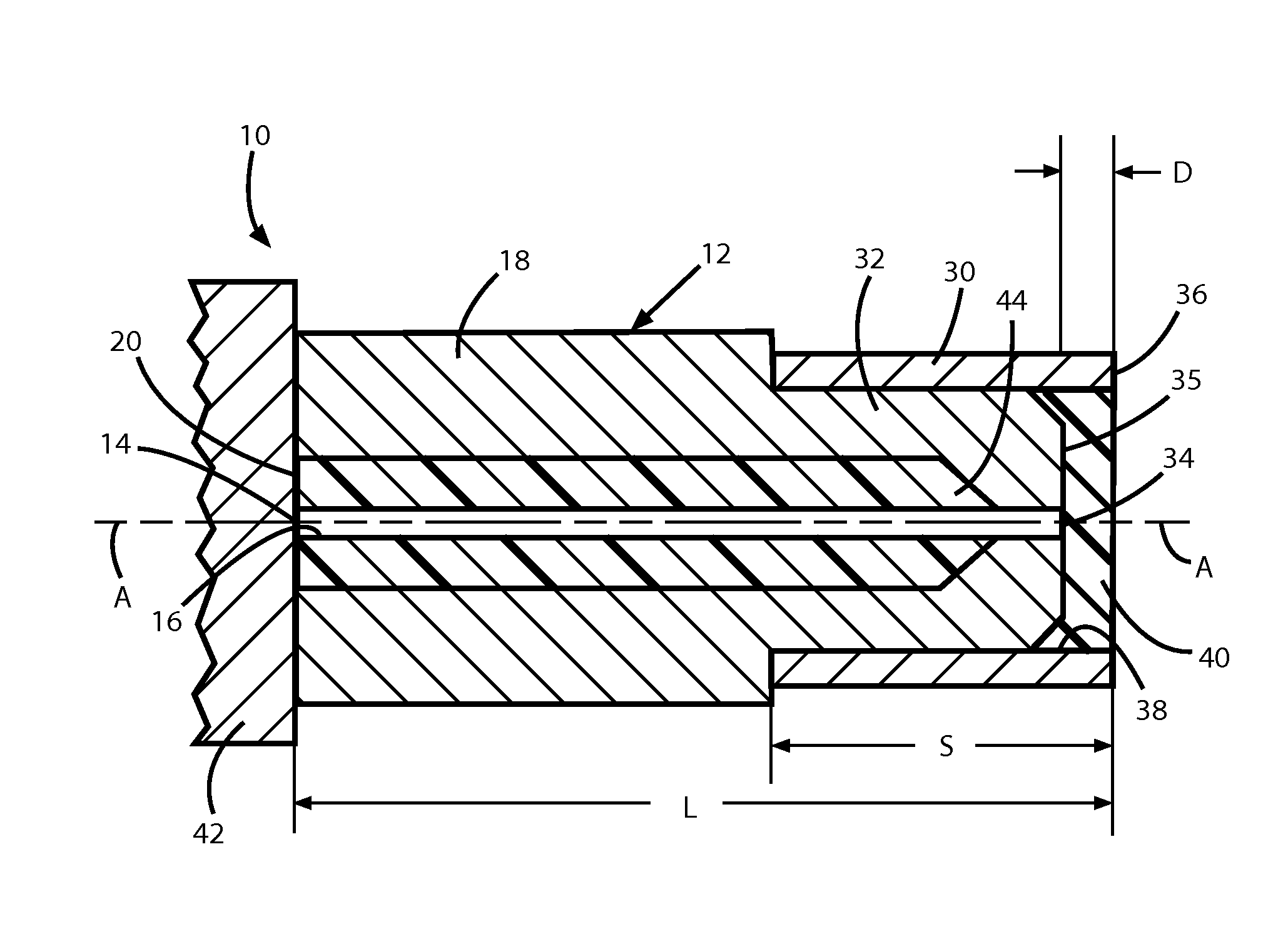
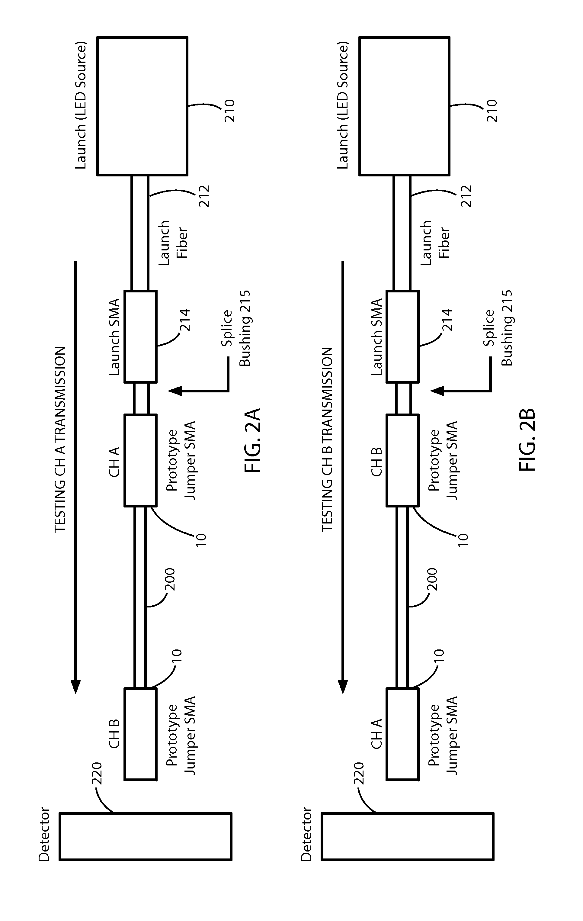
[0023]FIGS. 2(a) and 2(b) show transmission test measurement set-ups for the inventive connector 10 in FIG. 1. An approximately one meter length of a 50 μm / 60 μm / 70 μm glass / glass / polyimide fiber 200 (available from, e.g., Polymicro) is terminated at each end by a connector 10 constructed according to the invention. For the purpose of each set-up, the exact length of the fiber 200 is not critical. The refractive index (RI) of the fiber core is 1.46, and the RI of the epoxy barrier 40 formed at the end of the ferrule tip 32 of the connector 10 (see FIG. 1) is 1.53. In FIGS. 2(a) and 2(b), CH A connotes one of the inventive connectors 10 at one end of the fiber 200, and CH B connotes the other connector 10 at the opposite end of the fiber.

[0024]The output of a LED light source 210 (e.g., WT&T Model LE-IG-C) is coupled to one end of a launch fiber 212, the other end of which terminates in a standard “launch” SMA connector 214. In FIG. 2(a), the CH A connector 10 at the right end of the...

example two

[0027]A second test was performed on a lensed version of the inventive connector 10. In FIG. 3, parts of connector 110 that correspond to those of the connector 10 in FIG. 1 have corresponding reference numerals increased by 100.

[0028]In this Example, the single fiber 200 in FIGS. 2(a) and 2(b) was terminated at one end with the inventive connector 110, and at the opposite end with a conventional type SMA 905 fiber optic connector. To prepare the connector 110, the ferrule nose of an existing SMA 905 connector having a 77 μm thru-hole ferrule passage 116 was modified by turning down the outside diameter of the ferrule tip 132 from 0.125 inch to 0.085 inch over a length of 0.125 inch from the leading front surface 135 of the tip. The rear portion of the ferrule 118 was then advanced into the connector body 142 until a shoulder length of 0.384 inch between the front surface 135 of the ferrule tip 132 and the connector body 142 was obtained.

[0029]One end of the fiber 200 fiber was inse...


PUM

PropertyMeasurementUnit
distanceaaaaaaaaaa
lengthaaaaaaaaaa
thicknessaaaaaaaaaa

Abstract

A fiber optic connector has a connector body, an elongated ferrule supported in the connector body, and a sleeve fixed on the circumference of a distal tip of the ferrule. The ferrule has an axial passage that opens on a front surface of the tip so that an endface of a fiber retained in the passage is exposed at the front surface. Further, the sleeve has a leading edge that projects a determined distance axially beyond the front surface of the tip to form a recessed region in which the exposed endface of the fiber is set back from the leading edge of the sleeve. A barrier is contained in the recessed region for protecting the fiber endface from damage by surrounding objects. The barrier may include a cured epoxy layer, a lens, or a refractive index matching material optically aligned with the fiber endface.

Description

CROSS REFERENCE TO RELATED APPLICATION[0001]This application claims priority under 35 U.S.C. Section 119(e) of U.S. Provisional Patent Application No. 61 / 541,175 filed Sep. 30, 2011, entitled “Recessed Ferrule” which is incorporated by reference in its entirety.BACKGROUND OF THE INVENTION[0002]1. Field of the Invention[0003]The present invention relates generally to optical connectors, and particularly to an optical fiber connector construction and method of assembling same.[0004]2. Discussion of the Known Art[0005]Currently, most fiber optic connectors lack means for preventing ambient dirt and debris from depositing on a fiber endface that remains exposed at the tip of the connector while the connector is not in use. Such deposits will attenuate light signals transmitted through the connector when the connector is used in a fiber optic network. One known protective measure is to provide a removable end cap for the connector tip. Notwithstanding, persons forget or simply don't both...

Claims


Application Information

Patent Timeline
Patent Type & Authority Applications(United States)
IPC IPC(8): G02B6/36B23P11/00
CPCY10T29/49826G02B6/3849
Inventor BOUCHARD, KEVIN G.ZMURKO, MARK T.GOULD, BRADLEY
Owner OFS FITEL LLC
Why Eureka
Try Eureka