Device for splinting a cavity, organ duct and/or vessel

a technology for organs and splints, which is applied in the field of splinting devices for cavities, organ ducts and/or vessels, can solve the problems of serious illness risk, increased risk of snoring, and inability to register serious health risks, and achieves good physical tolerance, adapted flexibly, and avoid irritation of the pharynx and nausea.

Active Publication Date: 2013-04-11
DURING KLAUS
View PDF26 Cites 59 Cited by
  • Summary
  • Abstract
  • Description
  • Claims
  • Application Information

AI Technical Summary

Benefits of technology

[0013]In this way a device is created which, in the compressed state, is inserted in the cavity, organ duct and / or vessel after which, by drawing back an outer tube, the inner at least one stent is released, self-expands and, at least with the phase of greatest expansion, fits up against the wall of the cavity, organ duct and / or vessel. By pushing the tube back over the expanded stent, the device may be compressed again and easily removed from the cavity, organ duct and / or vessel. By means of the expanded stent, the cavity, organ duct and / or vessel is splinted and / or held open. The tube containing the compressed stent is so dimensioned that it may easily be inserted into the cavity, organ duct and / or vessel, even when the cavity, organ duct and / or vessel is in a collapsed state. Preferably the stent is made of a shape memory material. In the operating state, the device is expanded only over a small part in one phase of the stent, again preferably at the distal end, while the other part at the other end of the stent undergoes only a fairly limited expansion on release from the tube. The size and length relationships of the phases of the at least one stent relative to one another may be freely selected.
[0014]Due to the elastic construction of the stent and the elasticity of the surrounding tube, the device may easily follow any curvature of the cavity, organ duct and / or vessel. Optimal adaptation of the stent to the anatomy of the cavity, organ duct and / or vessel is possible with very great ease, due to the scope for varying the elastic expansion of the stent.
[0017]The material of the at least one stent may be provided with a coating, in particular with a bio-compatible surface coating, heparin, a carbonisation of nitinol, a nano-technological coating, x-ray-proof particles, a coating releasing an active substance, a preferably microporous bio-technological, or another other coating. Through the provision of such a coating, in addition to the physical effect, a pharmaceutical effect for example may also be provided. Moreover, by providing a coating which roughens the surface of the stent, fixing of the stent at the point of action is improved. In this connection, though, care is preferably taken to avoid any damage to the respective wall of the cavity, organ duct and / or vessel in the human or animal body in which the stent is used.
[0018]Preferably the at least one stent is / are made of a bio-compatible shape memory material, in particular a metal or a metal alloy, in particular a stainless steel or nitinol or another bio-compatible material, such as in particular a plastic, or monofile and / or multifile and / or composite glass fibres. Since the stent remains for at least several hours up to days in the human body, it is especially advantageous to use a bio-compatible material to avoid rejection effects and allergic reactions. To impress upon the stent the expanded form, with subsequent compression, and to allow it to open through self-expansion, a shape memory material is advantageously chosen.
[0021]To protect the stent from slipping into the cavity, organ duct and / or vessel, the stent may be provided at the proximal end with a fastening, which in a preferred embodiment may be adjusted variably to the anatomical features concerned in each case. The tube may be longer, the same length or shorter than the stent, and where necessary extended by an additional piece needed for handling, downwards from the stent, e.g. beyond the pulling element, and with which it may be adapted flexibly to the particular conditions of use. In a preferred manner of use, the device may be pushed forward directly up to the point of use and there released by withdrawing the tube from the stent. This may involve partial or complete withdrawal of the tube. In another preferred embodiment, the device may be pushed forward until just before the point of use only, and then the stent pushed out of the tube forward to the point of use, after which the tube is withdrawn wholly or partly or is even not withdrawn at all.
[0022]For the treatment of snoring and / or apnea the device is preferably so dimensioned that the distal end of the at least one stent just reaches the epiglottis, to avoid irritation of the pharynx and nausea. Here the distal expanded phase of the stent preferably has a length of 0.5 cm to 20 cm. The whole stent preferably has a length of 2 cm to 50 cm. The length of the tube is preferably between 0.5 cm and 50 cm. In a most preferred embodiment, the whole stent has a length of 10 cm to 35 cm with a distal expanded phase between 1 cm and 10 cm in length, and with a 10 cm to 35 cm long tube. It has been shown that, with such a device in the dimensions described and for human use, the air passages may be reliably and reproducibly held open during sleep, and the oxygen saturation in the blood for an apnea patient is able to rise above the critical limit value of 90%. Consequently, replacement of the n-CPAP breathing mask by the device according to the invention for the splinting and / or holding open of a cavity, organ duct and / or vessel is possible easily, efficiently and with very good physical tolerance by the patient.

Problems solved by technology

Through repeated and sometimes very frequent interruption of breathing during sleep, the patient is not adequately supplied with oxygen, in extreme cases leading to death.
Civilisation-related factors such as e.g. severe obesity or excessive alcohol consumption seriously increase the risk of illness.
Whereas people are aware of snoring, the serious risks to health especially of heavy snoring and of sleep apnea are often not registered, since the patient is not aware of the organic deficiency symptoms.
The relaxation of the tongue and of the surrounding muscles in the pharyngeal cavity which occurs during sleep leads, due to the inflowing air, to vibrations of the soft palate and the soft parts of the throat, resulting in the noise of snoring.
The interruption of breathing may last up to 1.5 minutes and be repeated 200-400 times during the night, which does not allow the patient any deep sleep.
The consequences are restless sleep, tiredness during the day, high blood pressure, lack of drive, etc.
If the illness is not treated, then the body is unable to regenerate adequately in sleep, leading to a lower expectation of life.
Increased fluctuations of pressure within the thorax may in certain circumstances have adverse effects on the cardiovascular system.
It is nowadays assumed that in particular during sleep apnea, but also during snoring, significant organic consequent illnesses may occur.
Significant drawbacks to this standard therapy, which is to date the sole treatment option with medical effectiveness, are the discomforts to the patient, created above all by the wearing of an airtight oxygen mask for the whole night, fixed via an adequately strong headband and connected via the supply tube to the breathing apparatus; also through drying out of the mucous membranes and the need for moistening of the respiratory air, plus the operating noise of the breathing apparatus.
In addition to the severely restricted freedom of movement during sleep, there is the risk of air escaping due to leaks between the breathing mask and the skin of the face, so that the overpressure is accidentally reduced and may no longer be sufficient.
Moreover, acceptance of the nightly wearing of a breathing mask is very limited in time for many patients, even though life-long therapy is required.
A further drawback of the CPAP mask is the need to take the breathing apparatus with one when travelling.
There is also the time and effort required for cleaning and maintenance.
The prevailing view is that as yet no efficient alternative treatment option has been developed which may be used routinely, and is also practicable and cost-effective.
A large number of proposals have been made for the physical prevention of snoring and apnea, but none have become established on the market.
A drawback cited by the inventor is the need to overcome nausea.
Experience shows that the route described here, via the mouth, is impracticable, and does not lead to adequate reduction of symptoms.
Alternatively, in WO 98 / 23233 it is proposed to introduce a double tube through the nose to maintain the air supply passage, but this is just as ineffective as the two instruments described above.

Method used


Image

  • Device for splinting a cavity, organ duct and/or vessel
  • Device for splinting a cavity, organ duct and/or vessel
  • Device for splinting a cavity, organ duct and/or vessel

Examples


Embodiment Construction

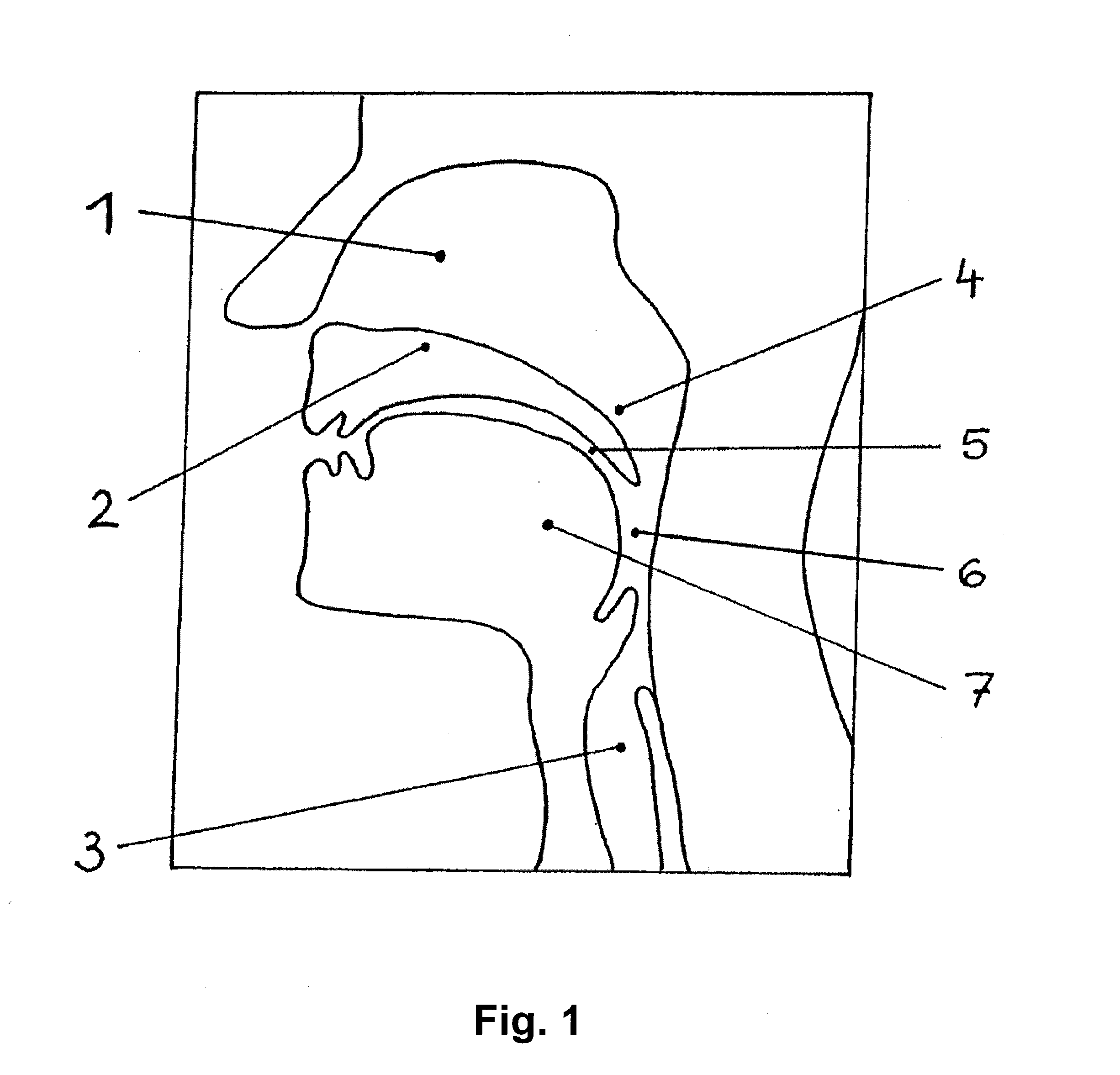
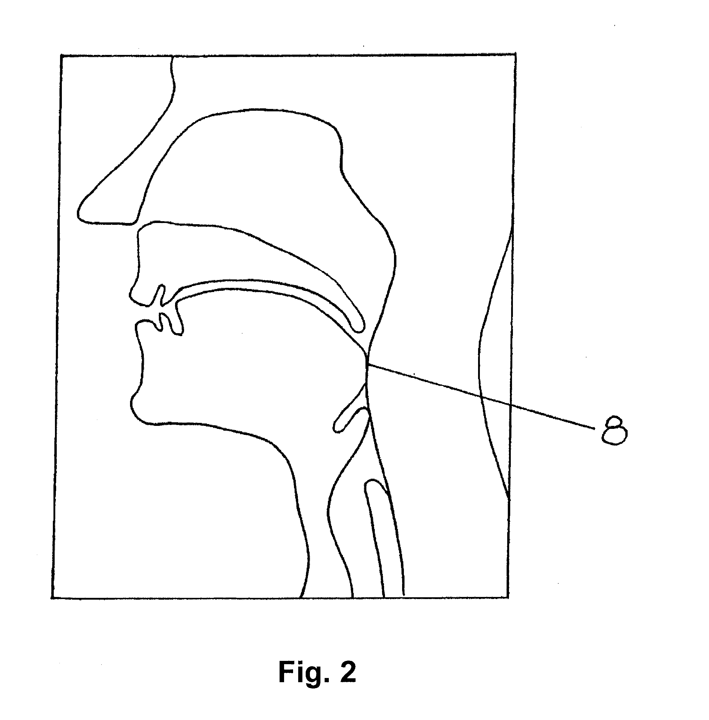
[0033]FIG. 1 shows the nasal chamber (1), the hard palate (2), the trachea (3), the soft palate (4), the oral cavity (5), the free airways (6) and the tongue (7). Illustrated is the free airway during sleep of a healthy person. FIG. 2 shows the closed airway (8) in the pharynx, as occurs in obstructive sleep apnea. FIG. 3 shows the use of the n-CPAP breathing apparatus with the breathing mask (9) in place, and the air passages opened by the overpressure.

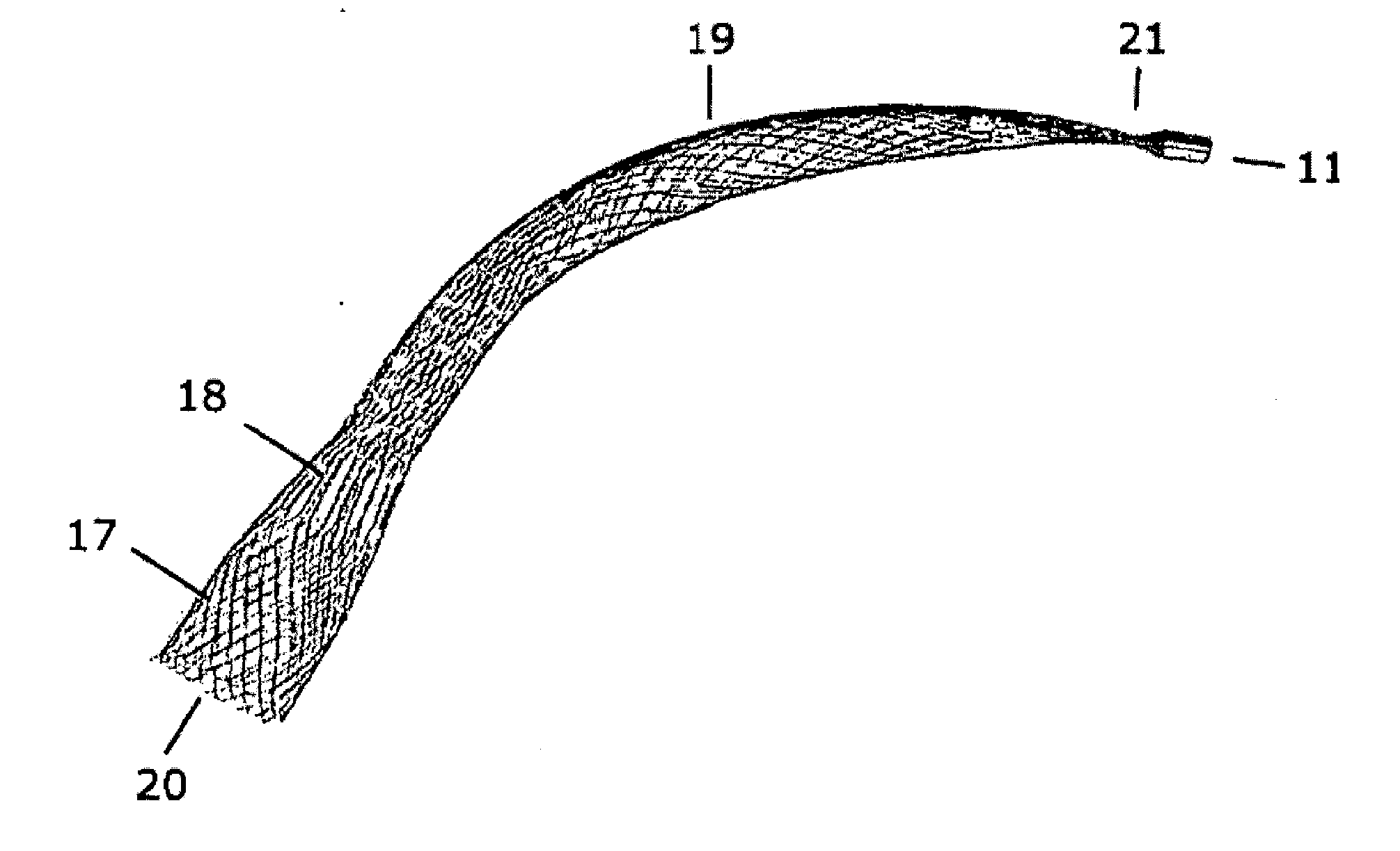
[0034]FIG. 4 shows a view of the components of a first embodiment of a device according to the invention for the splinting and / or holding open of a cavity, organ duct and / or vessel in a human or animal body. The device comprises a three-phase stent (10), connected at its proximal end (21) via a connecting element (11) to the connecting element (12) of a pulling element (13). To insert the stent into the cavity, organ duct and / or vessel, the stent is inserted into the tube (14) and compressed. At its proximal end (21), the stent (10) ...


PUM

PropertyMeasurementUnit
lengthaaaaaaaaaa
lengthaaaaaaaaaa
lengthaaaaaaaaaa

Abstract

The invention relates to a device for splinting and / or maintaining a cavity, an organ duct and or a vessel in a human or animal body, said device including at least one compressible and self-expanding stent that is composed of at least three phases.

Description

CROSS REFERENCE TO RELATED APPLICATIONS[0001]This is a Continuation-in-Part Application claiming priority to co-pending U.S. patent application Ser. No. 12 / 096,457 filed on Aug. 12, 2010, which in turn was filed under the provisions of 35 U.S.C. §371 and claims the priority of International Patent Application No. PCT / EP2006 / 002137 filed on Dec. 1, 2006, which in turn claims priority of German Patent Application No. 10 2005 058 242.7 filed on Dec. 6, 2005 and German Patent Application No. 10 2006 040 301.0 filed on Aug. 29, 2006.BACKGROUND OF THE INVENTION[0002]1. Technical Field[0003]The present invention relates to a device for the splinting and / or holding open of a cavity, an organ duct and / or a vessel in the human or animal body with at least one compressible and self-expanding stent which has at least one expanded phase.[0004]2. Prior Art[0005]Syndromes based on the at least partial closure of cavities, organ ducts and / or vessels are increasing sharply due to the effects of civi...

Claims


Application Information

Patent Timeline
Patent Type & Authority Applications(United States)
IPC IPC(8): A61F2/82A61F2/86D04C1/06A61F5/56A61F2/90A61F2/966
CPCA61F2/82A61F5/56A61F2/86D04C1/06D10B2509/06A61F2/91A61F2/962A61F2250/0039A61F2250/0048A61F2/90A61F5/566A61F2/186A61F2/203A61F2250/0067
Inventor MAHR, RICHARDPFEFFER, JOACHIN GEORG
Owner DURING KLAUS
Why Eureka
Try Eureka