
Ozone injection for continuous flow cleaning systems

a technology of ozone injection and continuous flow, which is applied in the direction of floor cleaning machines, vacuum cleaners, cleaning using liquids, etc., can solve the problems of large safety provisions, complex installation, and inefficient ozone source, and achieve the effect of high ozone injection efficiency, efficient cleaning, and avoiding technical and environmental challenges

Active Publication Date: 2013-04-18
MINUTEMAN INT
View PDF11 Cites 8 Cited by
  • Summary
  • Abstract
  • Description
  • Claims
  • Application Information

AI Technical Summary

Benefits of technology

The present invention provides a floor cleaning machine that uses a compact, self-contained, environmentally clean, economical, safe and energy efficient water purification system. The machine uses liquid ozone which is introduced directly into a circulating cleaning solution for cleaning virtually any type of floor in a safe and economical manner. The ozone in liquid form maintains a cleaning solution circulating in a closed system in a highly purified state by generating the ozone at its point of use to accommodate ozone's short half life, provide high efficiency of the ozone introduced into the cleaning solution, and avoid the technical and environmental challenges associated with ozone in the gaseous state. The floor cleaning machine includes a vacuum nozzle, liquid cleaning solution reservoir, floor scrubbing assembly, motor, fluid conveying system, and ozone cell for eliminating pathogens in the cleaning solution.

Problems solved by technology

Ultraviolet ozone generation has been used primarily in air ducts and for the preservation of food and is a relatively inefficient source of ozone.
Although more energy efficient than the UV radiation approach to producing ozone, the corona discharge approach is also a relatively inefficient source of ozone and requires extensive safety provisions and complex installations because of the high voltages involved in this approach for ozone production.
One problem that this approach arises from the propensity of ozone to act as a strong irritant causing discomfort to the eyes and throats of those in the vicinity of the ozone source.
In addition, this approach uses the relatively inefficient approach of ultraviolet light generation of ozone which, as discussed above, is much less energy efficient than even the corona discharge approach to ozone generation.

Method used


Image

  • Ozone injection for continuous flow cleaning systems
  • Ozone injection for continuous flow cleaning systems
  • Ozone injection for continuous flow cleaning systems

Examples


Embodiment Construction

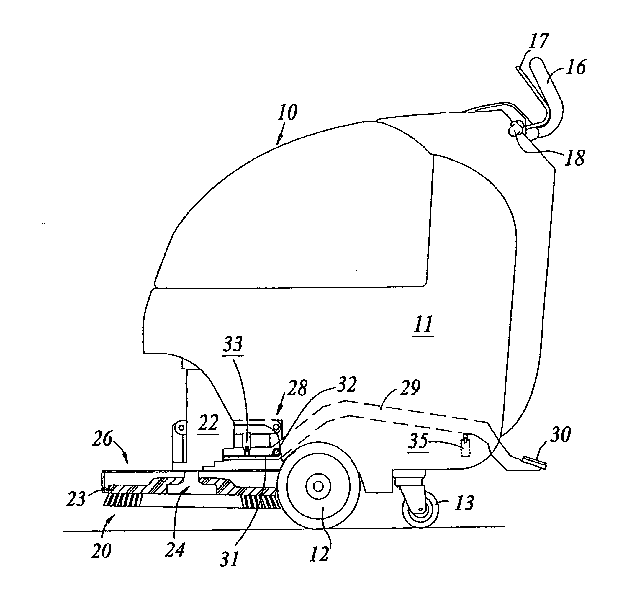
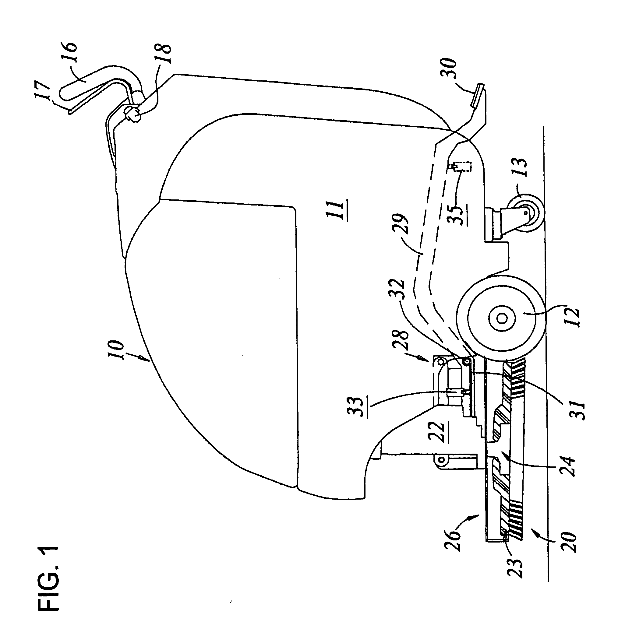
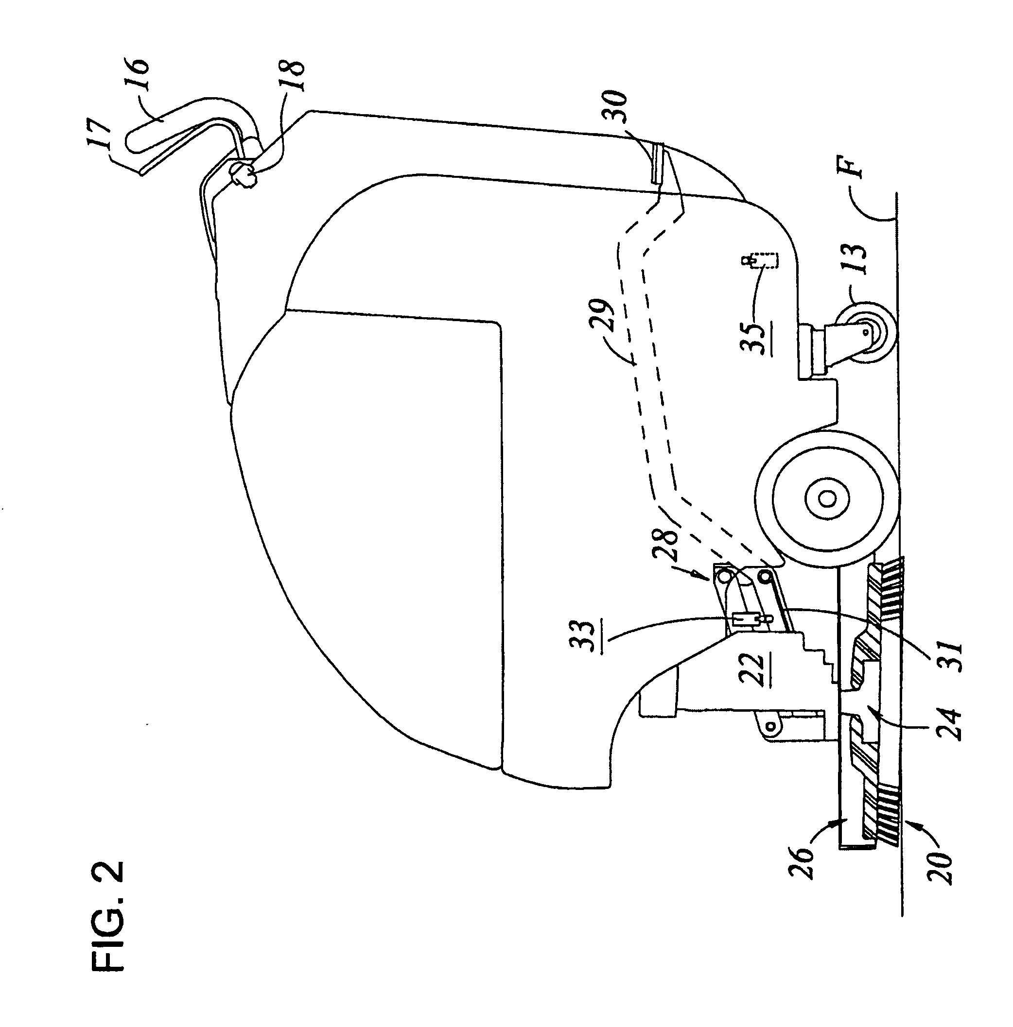
[0022]Referring first to FIG. 1, reference numeral 10 generally designates a typical floor scrubbing machine for carrying out the present invention. The machine includes an outer housing or casing 11 and is supported by forward wheels 12, as well as two rear caster wheels 13. Some machines may only employ two wheels such as a carpet extractor. In addition, this invention can be used on very hard floors such as of hardwood, tile, concrete, etc., as well as on soft surfaces such as of plush carpeting or other soft material and can also be used on a wide range of floor textures.

[0023]Within the housing 11 are batteries for powering the machine, a reservoir of cleaning fluid for application to the scrub brush or directly to the floor, with a rear suction device for recovering spent solution and a storage tank for tile spent solution, all of which are conventional and not shown in detail. While the floor scrubbing machine in the described embodiment is powered by batteries, it could equa...


PUM


Abstract

A mobile floor cleaning machine has a clean water system with a reservoir for applying water to a floor during cleaning. The floor cleaning machine includes an ozone source which generates ozone in liquid form and introduces the liquid ozone directly into the circulating water for eliminating pathogens in the circulating water. The ozone is generated continuously and essentially instantaneously by the ozone source and destroys most bacteria, virus, fungus and mold in the circulating water at room temperature, while decaying harmlessly to oxygen within the water and producing fewer by-products than chemical sanitizers and having essentially no environmental impact.

Description

FIELD OF THE INVENTION[0001]This invention relates generally to mobile floor cleaning machines and is particularly directed to a self-contained arrangement for continuously purifying the circulating water used to clean a floor during on-the-go operation of the floor cleaning machine.BACKGROUND OF THE INVENTION[0002]Ozone is a highly reactive substance which naturally occurs as a gas comprised of three bonded oxygen atoms. Common uses of ozone include the treatment of drinking and swimming pool water, the treatment of industrial waste, the bleaching of inorganic products such as clay, and as a disinfectant. Ozone is formed by breaking apart diatomic oxygen molecules, with the free oxygen atoms thus produced reacting with conventional diatomic oxygen molecules to form ozone. In the past, two methods have been used to produce ozone for commercial purposes. These two methods involve ultraviolet (UV) radiation and corona discharge. Ultraviolet ozone generation has been used primarily in ...

Claims


Application Information

Patent Timeline
Patent Type & Authority Applications(United States)
IPC IPC(8): A47L11/30A47L11/40B08B3/08A47L7/00
CPCA47L11/4083A47L11/283
Inventor POLLACK, JEFFREY W.
Owner MINUTEMAN INT
Learn More