Thermally oxidized seed layers for the production of textured electrodes and pzt devices and method of making

a technology of textured electrodes and seed layers, applied in the direction of piezoelectric/electrostrictive device details, device material selection, device details, etc., can solve the problems of reducing reliability properties including polarization-retention and polarization-cycling endurance, placing very strict requirements on single crystal substrates, etc., to achieve optimal texturing

Inactive Publication Date: 2013-04-18
ARMY UNITED STATES GOVERNMENT AS REPRESENTED BY THE SEC OF THE ARMY THE
View PDF6 Cites 26 Cited by
  • Summary
  • Abstract
  • Description
  • Claims
  • Application Information

AI Technical Summary

Benefits of technology

[0016]Some advantages of using the inventive thermally oxidized metal seed layers include: 1) the system is self-seeding i.e. there is no need for an additional seed layer containing other elements, 2) only a single source material and deposition method is required to obtain the metal thin film, 3) metal thin films typically grow with natural textures at temperatures below 600° C. which is readily achievable in production thin film deposition tools, 4) The oxidation process can be completely separated from the deposition process such that higher temperature anneal processes can be completed in an oven instead of the metal deposition tool, and 5) both the metal thin film deposition process and the oxidation processes can be used to tune the physical structure of the seed layer to obtain optimal texturing of the overlying electrode and PZT films.

Problems solved by technology

The difficulty with this approach is that it places very strict requirements on the single crystal substrate, and the electrode must provide an epitaxial relationship with both the single crystal substrate and the ferroelectric film.
Unfortunately, such seed layers introduce composition gradients that cause a reduction in the reliability properties including polarization-retention and polarization-cycling endurance.

Method used


Image

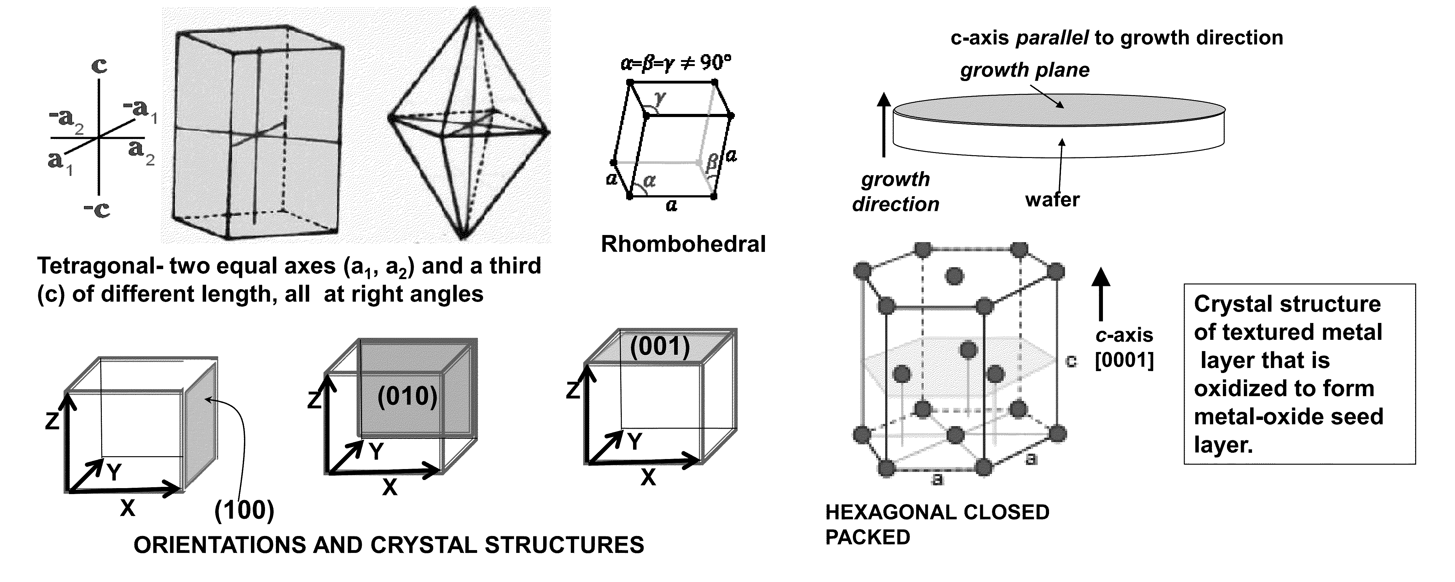
  • Thermally oxidized seed layers for the production of  textured electrodes and pzt devices and method of making
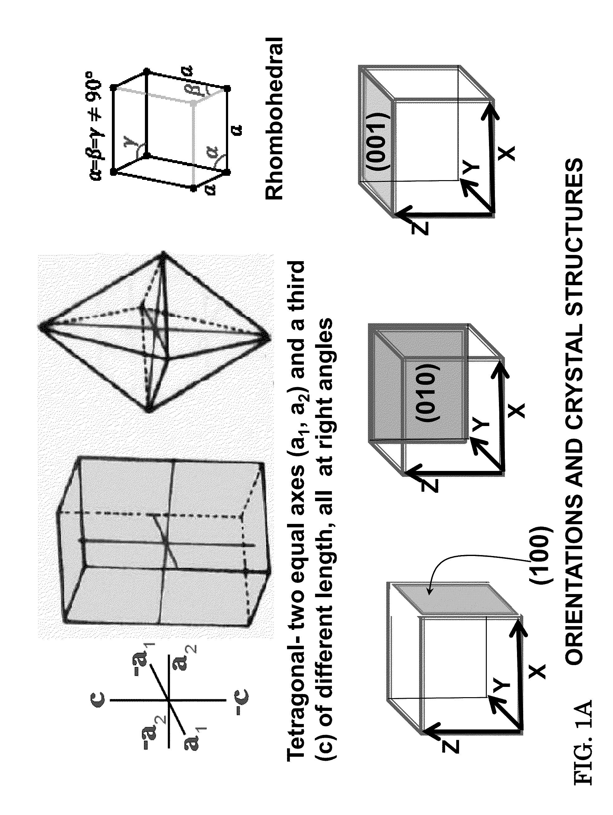
  • Thermally oxidized seed layers for the production of  textured electrodes and pzt devices and method of making
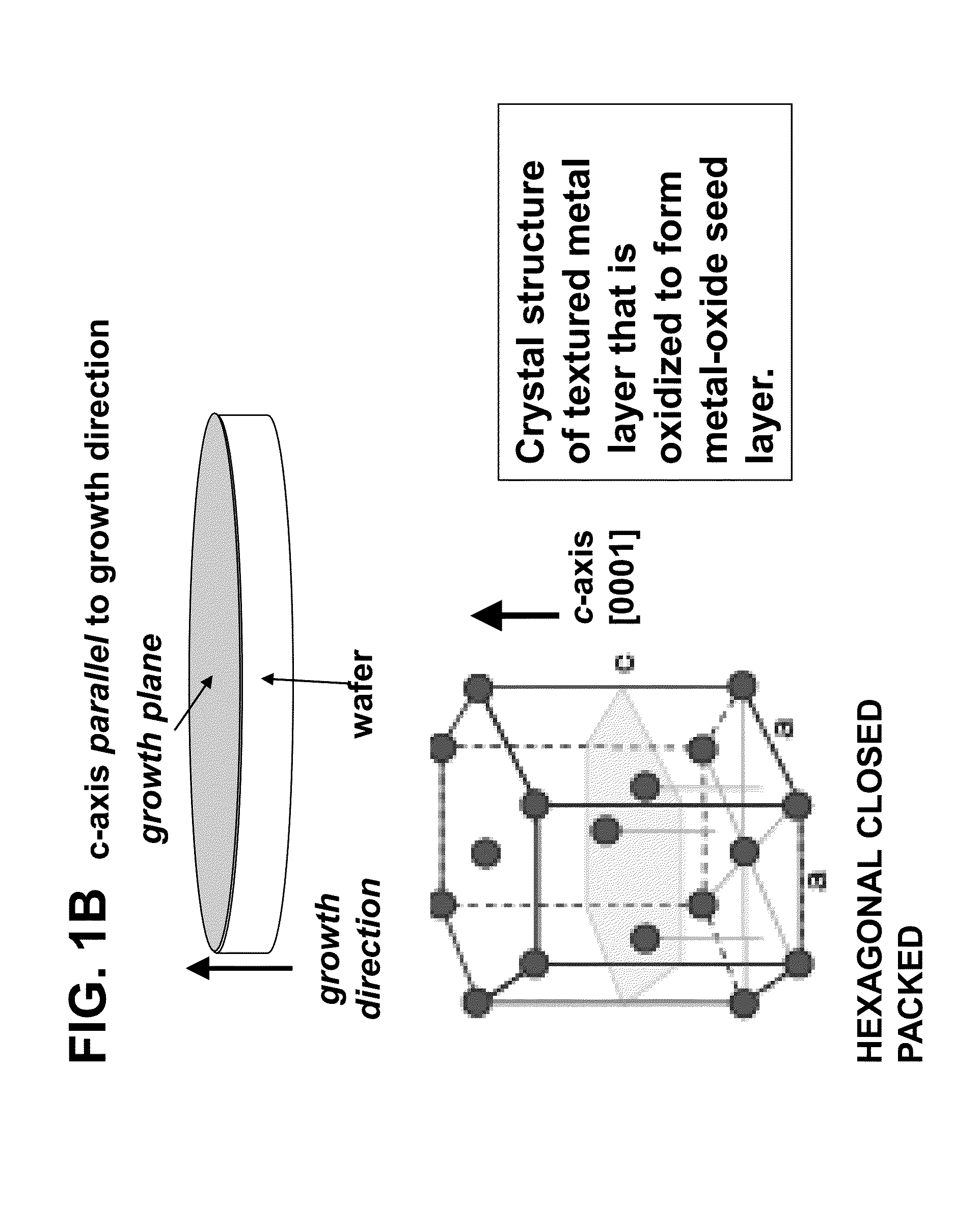
  • Thermally oxidized seed layers for the production of  textured electrodes and pzt devices and method of making

Examples


Embodiment Construction

[0048]The embodiments herein and the various features and advantageous details thereof are explained more fully with reference to the non-limiting embodiments that are illustrated in the accompanying drawings and detailed in the following description. Descriptions of well-known components and processing techniques are omitted so as to not unnecessarily obscure the embodiments herein. The examples used herein are intended merely to facilitate an understanding of ways in which the embodiments herein may be practiced and to further enable those of skill in the art to practice the embodiments herein. Accordingly, the examples should not be construed as limiting the scope of the embodiments herein.

[0049]The terminology used herein is for the purpose of describing particular embodiments only and is not intended to limit the full scope of the invention. As used herein, the singular forms “a”, “an” and “the” are intended to include the plural forms as well, unless the context clearly indica...


PUM


Abstract

A method for forming an electrical device having a {100}-textured platinum electrode comprising: depositing a textured metal thin film onto a substrate; thermally oxidizing the metal thin film by annealing to convert it to a rocksalt structure oxide with a {100}-texture; depositing a platinum film layer; depositing a ferroelectric film. An electrical device comprising a substrate; a textured layer formed on the substrate comprising metal oxide having a rocksalt structure; a first electrode film layer having a crystallographic texture acting as a template; and at least one ferroelectric material layer exhibiting spontaneous polarization epitaxially deposited on the first electrode film layer whereby the rocksalt structure of the textured layer facilitates the growth of the first electrode film layer with a {100} orientation which forms a template for the epitaxial deposition of the ferroelectric layer such that the ferroelectric layer is formed with an {001} orientation.

Description

CROSS-REFERENCE TO RELATED APPLICATIONS[0001]This application claims priority to U.S. Provisional Application No. 61 / 547,879 entitled “Thermally Oxidized Seed Layers for the Production of {001} Textured Electrodes and PZT Capacitors” by Fox, et al filed on Oct. 17, 2011, hereby incorporated by reference. This application is also a continuation-in-part (CIP) of U.S. patent application Ser. No. 13 / 436,349 entitled “Stylo-Epitaxial Piezoelectric and Ferroelectric Devices and Method of Manufacturing,” filed Mar. 30, 2012, which claims priority to U.S. Provisional Application No. 61 / 547,990 entitled “Stylo-Epitaxial Piezoelectric and Ferroelectric Devices and Method of Manufacturing,” filed by Fox, et al. on Oct. 17, 2011, both of which are hereby incorporated by reference.STATEMENT OF GOVERNMENT INTEREST[0002]The embodiments herein may be manufactured, used, and / or licensed by or for the United States Government without the payment of royalties thereon.BACKGROUND OF THE INVENTION[0003]A...

Claims


Application Information

Patent Timeline
Patent Type & Authority Applications(United States)
IPC IPC(8): H01L41/04C30B23/08H01L41/16C30B25/02H01L41/053C30B23/02C30B25/06
CPCC30B23/02C30B29/02C30B29/32H01L41/319H01L41/0815H01L41/1876H01L41/318H01L41/081H10N30/10513H10N30/10516H10N30/8554H10N30/079H10N30/078
Inventor FOX, GLEN R.POLCAWICH, RONALD G.POTREPKA, DANIEL M.
Owner ARMY UNITED STATES GOVERNMENT AS REPRESENTED BY THE SEC OF THE ARMY THE
Why Eureka
Try Eureka