System And Method To Monitor And Control Remote Sensors And Equipment

a technology for remote sensors and equipment, applied in the field of systems and methods for monitoring sensors of equipment and/or controlling equipment, can solve the problems of affecting the operation of the machin

Active Publication Date: 2013-04-18
BLUETICK
View PDF5 Cites 33 Cited by
  • Summary
  • Abstract
  • Description
  • Claims
  • Application Information

AI Technical Summary

Benefits of technology

[0012]The systems and methods of the invention as presented herein are directed to solving one or more of the problems identified above. Additional features and advantages of the invention will be set forth in the description that follows, and in part will be ap...

Problems solved by technology

Industrial equipment, such as the just mentioned machines used in the oil and natural gas industry, is often located in areas that are so remote that access to hardwired communication lines is often unavailable.
Even a seemingly minor failure of a first machine can induce a major failure of an associated second machine.
As used herein, a minor failure is one that does not cause complete stoppage of a machine, while a major failure can cause complete stoppage of a machine, environmental damage, or even loss of life or property.
Because of the remoteness of many sites, and despite the need for frequent monitoring and control of the equipment at these sites, most sites receive only routine periodic visits for purposes of maintenance.
Routine periodic visits may maintain the machines in working order, but there are times when routine periodic visits are insufficient.
For example, a coolant level in a radiator of a pump motor might be routinely inspected once a month, however, an unexpected coolant leak might occur shortly after a physical inspection.
Before the next physical inspection occurs, the radiator might become inefficient causing the pump motor to run hot and eventually seize, resulting in a major failure of the pump motor.
Unfortunately, this situation does not exist.
Even if some solution to the problem of the lack of any means to promptly, or even spontaneously, collect the status of machines at a given site existed, the problem of communicating the collected status to a person responsible for maintaining the machines is still present.
Today, there are no known sites that contain an integra...

Method used


Image

  • System And Method To Monitor And Control Remote Sensors And Equipment
  • System And Method To Monitor And Control Remote Sensors And Equipment
  • System And Method To Monitor And Control Remote Sensors And Equipment

Examples


Embodiment Construction

[0027]The systems and methods described herein address both the problems identified above and other problems as understood by those of skill in the art.

[0028]Although the systems and methods described herein are exemplified by embodiments and applications in the fields of petroleum and / or natural gas, the invention is not limited to these fields.

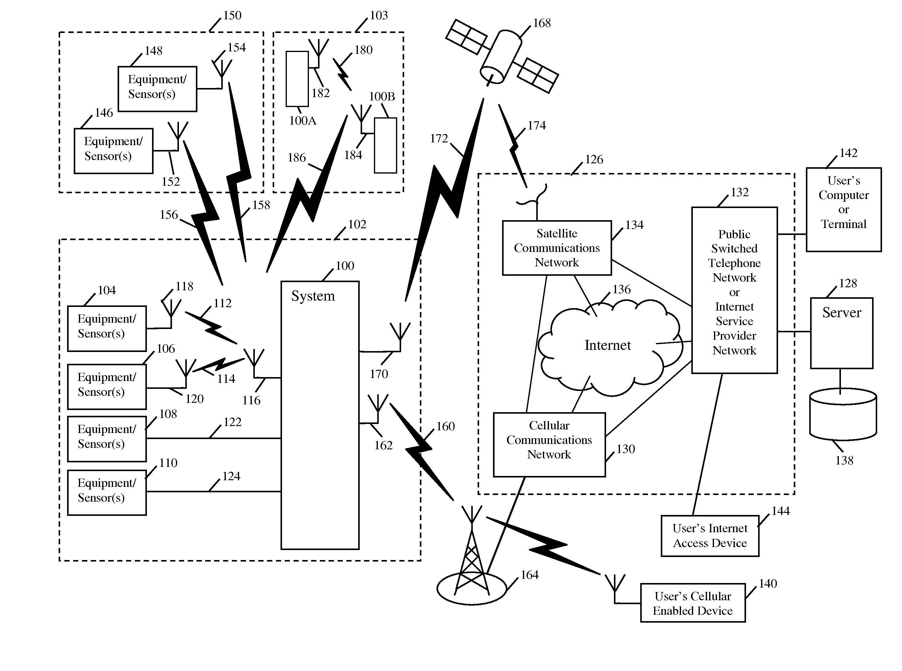
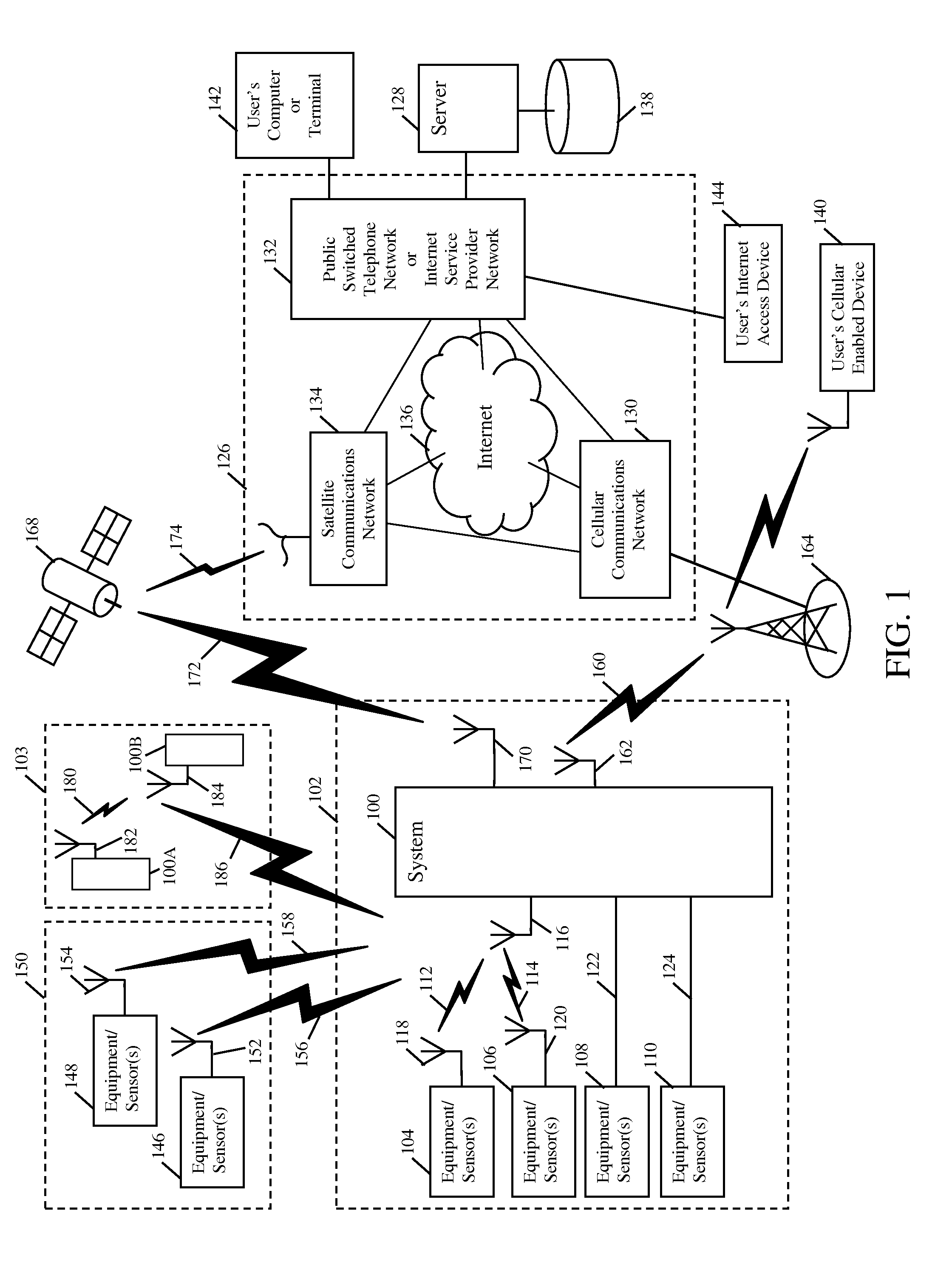
[0029]FIG. 1 is a block diagram illustrating an interrelationship between a system 100 in accordance with an embodiment of the invention and other devices, systems (both similar and dissimilar to system 100), and networks that may be interfaced thereto. Embodiments of the invention as disclosed herein overcome the problems associated with providing a system 100, configured to control and / or monitor equipment / sensor(s) 104, 106, 108, 110, at a new or existing site 102 that does not have hardwired communications connections and / or electrical power available for use by the system 100. Embodiments of the invention as disclosed herein may be powe...


PUM


Abstract

A processor, memory, first transceiver, second transceiver, plurality of wired and wireless ports, and a power system storing excess energy are provided. Multiple similar systems may mesh communication via first transceiver. Unencrypted data from ports are packaged into unencrypted data structures and forwarded to the second transceiver for transmission according to the telecommunications standard of the second transceiver. A method may include determining if either a predefined time to sample data was reached or if an interrupt was received, and then sampling ports associated with the predefined time or interrupt, to collect data from remote sensors or equipment coupled to the ports, process the sampled data, store the processed data in memory, and evaluate the stored data against a set of rules. If no rules are violated, the sampling continues, and the processed data is packaged and transmitted to a server at a prescheduled time. Actions are taken if rules are violated.

Description

BACKGROUND OF THE INVENTION[0001]The present invention relates to systems and methods for monitoring sensors of equipment and / or control of equipment. More specifically, the present invention relates to the monitoring and control of equipment that operates with little, if any, human intervention. Even more specifically, the present invention relates to self-sustaining, autonomous, monitoring, reporting, and control systems powered by renewable energy.[0002]Machines that operate for the most part without human intervention are ubiquitous in our society. Familiar examples of such machines include the electric motors and associated compressors of residential refrigerator and air conditioning units used in our homes. Less familiar machines that operate for the most part without human intervention may be located far from our communities, in locations that are often unobserved by the public and unfrequented by even the persons that own or operate the machinery. Examples of these machines ...

Claims


Application Information

Patent Timeline
IPC IPC(8): H04W92/00H04B7/14
CPCH04W24/06H04B7/18523H04W52/02H02J13/00028Y02D30/70H04L12/66H04W24/10H04W92/02
Inventor MILLS, MICHAEL C.KRUPINSKI, III, MATTHEW P.CHIAPPETTA, LUIS G. RODRIGUEZFONS, BENJAMIN ALLEN
Owner BLUETICK
Why Eureka
Try Eureka