Gear cutting machine, end mill and method of form milling

a cutting machine and end mill technology, applied in the direction of gear teeth, gear tooth manufacturing apparatus, manufacturing tools, etc., can solve the problems of inability to select the ideal cutting speed for rotational movement, inability to meet the needs of the customer, etc., to achieve short workpiece machining time, reduce wear phenomena, and increase cutting speed

Inactive Publication Date: 2013-04-25
LIEBHERR VERZAHNTECHNIK GMBH
View PDF6 Cites 11 Cited by
  • Summary
  • Abstract
  • Description
  • Claims
  • Application Information

AI Technical Summary

Benefits of technology

[0019]The procedure in accordance with the present disclosure reduces the wear phenomena at the end mill used or keeps it constant over the total blade length. The method furthermore allows a simplified selection of an ideal cutting speed for operatin...

Problems solved by technology

The selection of an ideal cutting speed for the rotational movement is not possible due to the diameter difference.
The possible cutter service life is furthermore disadvantageously impaired by it.
To avoid a partial overload of the cutter, the cutter speed accordingly has to be adapted, which can result in longer mac...

Method used


Image

  • Gear cutting machine, end mill and method of form milling
  • Gear cutting machine, end mill and method of form milling
  • Gear cutting machine, end mill and method of form milling

Examples


Embodiment Construction

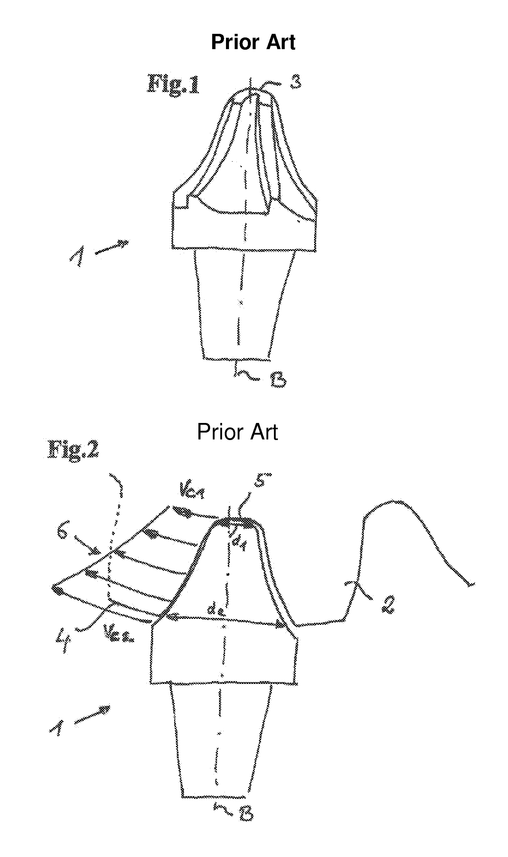
[0029]FIGS. 1 and 2 were already discussed in the introductory part of the description so that details on the shown representations will not be discussed again in this part of the description.

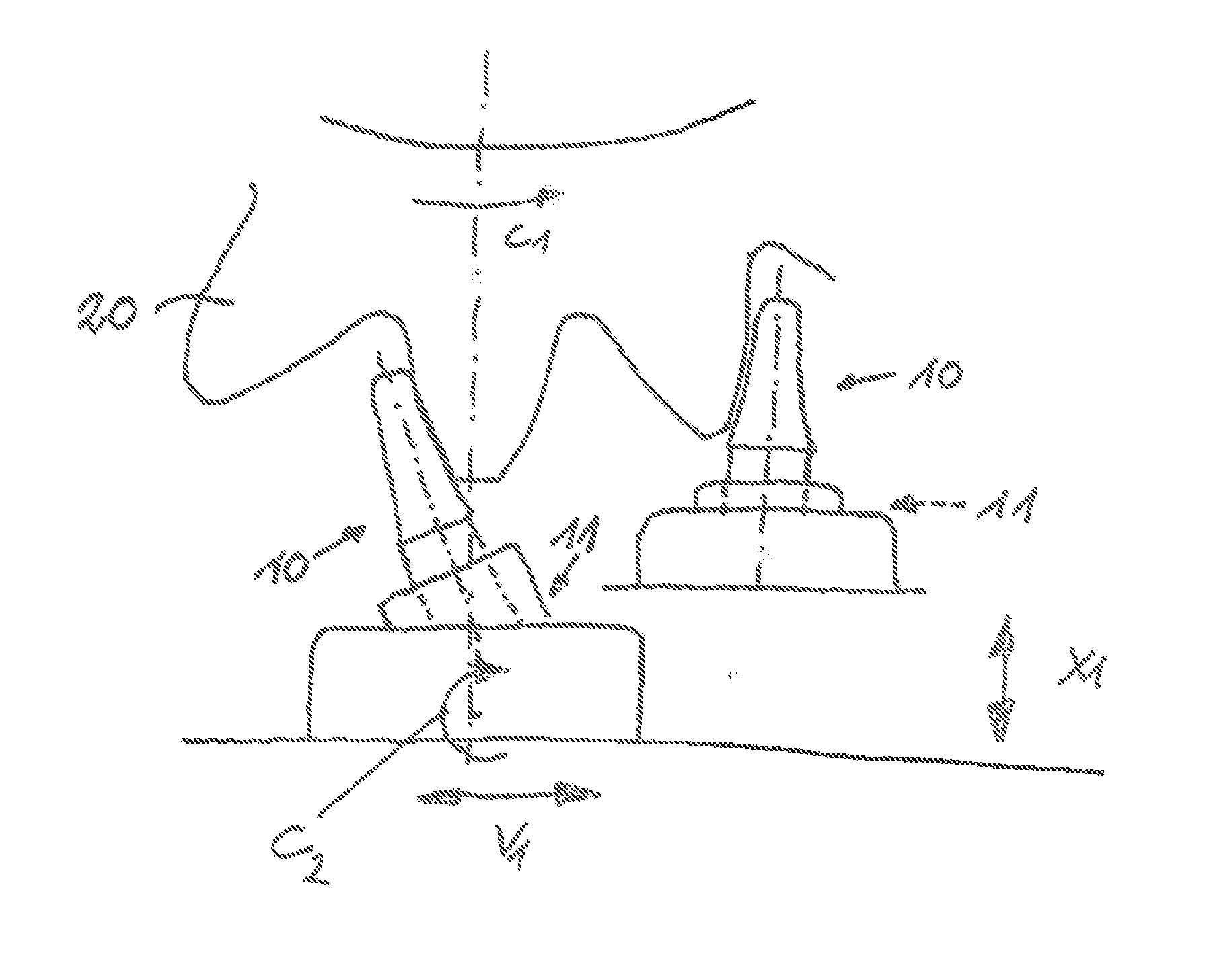
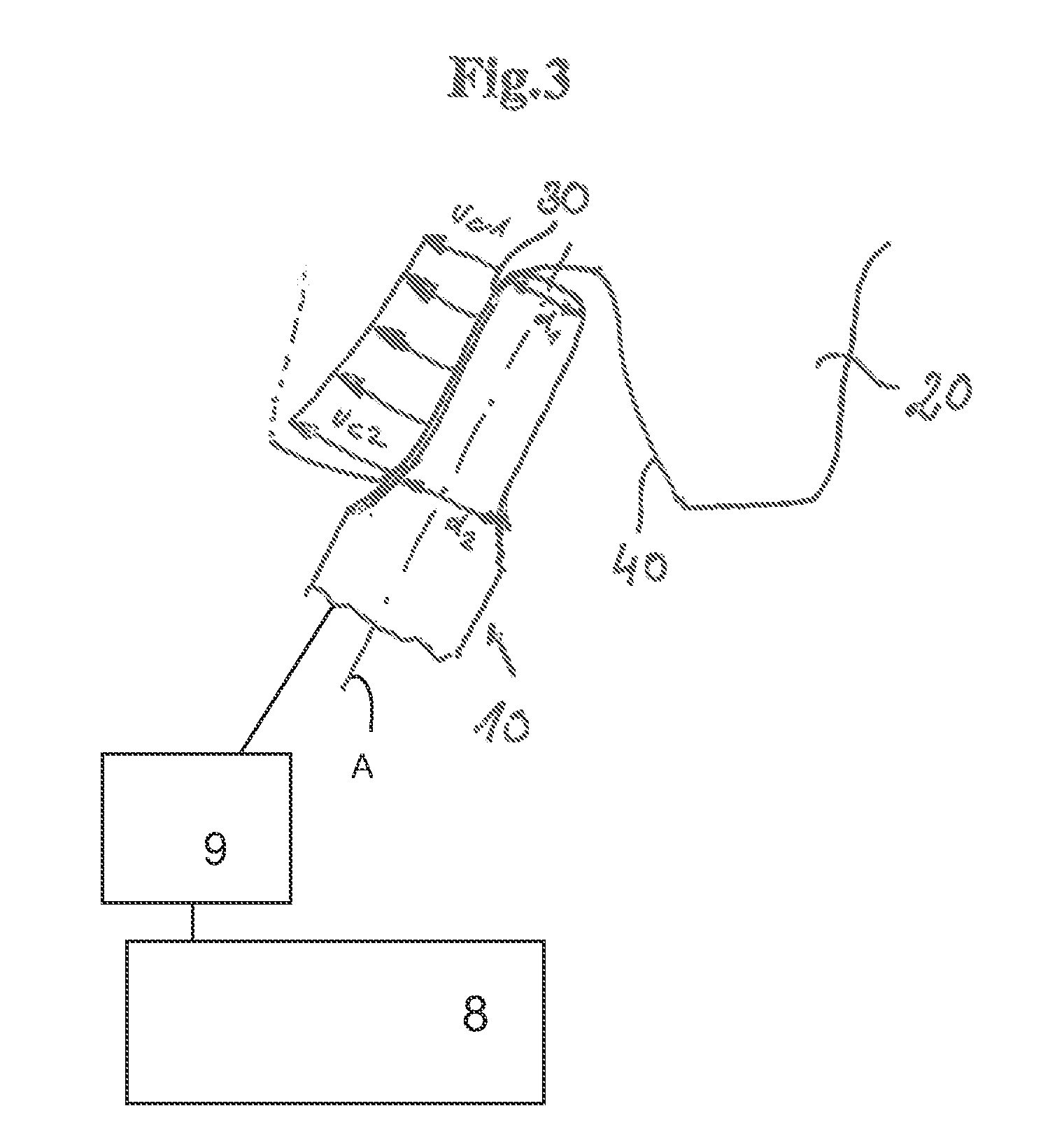
[0030]FIG. 3 shows a schematic representation of the end mill 10 in accordance with the present disclosure in the gear cutting of the workpiece in the form of a toothed wheel 20 having an involute toothing. The end mill 10 is mounted at the cutter head 9 of the CNC gear cutting machine 8 in accordance with the present disclosure and is set into rotation about the cutter axis A. The resulting tool speed is designated by n and is given in revolutions per minute. The machine kinematics align the end mill 10 in accordance with the machining of the tooth flanks of the toothed wheel 20. In this respect, either the cutter or the tool mount together with the workpiece can be moved or both in combination. The gear cutting machine 8 may include one or more control units receiving information from one or ...


PUM

PropertyMeasurementUnit
Diameteraaaaaaaaaa
Cutting speedaaaaaaaaaa

Abstract

The present disclosure relates to a gear cutting machine for gear cutting a workpiece, in particular a toothed wheel, by form milling having at least one cutter head for mounting at least one end mill, wherein the cutter head or the end mill and/or the workpiece mount are adjustable and the end mill axis can be aligned approximately parallel to the machined tooth flank of the clamped workpiece, and wherein the cutter axis can be applied to the flank contour and the end mill has an outer contour corresponding to the flank contour.

Description

CROSS REFERENCE TO RELATED APPLICATION[0001]This application claims priority to German Patent Application No. 10 2011 017 411.7, entitled “Gear cutting machine, end mill and method of form milling”, filed Apr. 18, 2011, which is hereby incorporated by reference in its entirety for all purposes.TECHNICAL FIELD[0002]The present disclosure relates to a gear cutting machine for gear cutting a workpiece, in particular a toothed wheel, by form milling using an end mill.BACKGROUND AND SUMMARY[0003]Tooth form mills in the form of end mills are used on gear cutting machines for gear cutting toothed wheels and for milling worm gears in accordance with the forming method. The use of such end mills starts with toothed wheels at, for instance, module 10 and extends up to the largest gear cutting dimensions. When milling worm gears, these end mills are also used with a much smaller module for worm gears and worm wheels.[0004]Tools in end mill form or, even better, side milling cutters are also us...

Claims


Application Information

Patent Timeline
IPC IPC(8): B23F1/06B23F21/12
CPCB23C5/10B23C2210/084B23F1/06Y10T409/103975B23F21/122Y10T407/1745Y10T409/103816B23F21/12Y10T409/10795Y10T409/108109Y10T409/108745
Inventor MUNDT, ALOIS
Owner LIEBHERR VERZAHNTECHNIK GMBH
Why Eureka
Try Eureka