Apparatus and method for measuring the dissipation factor of an insulator

a technology of dissipation factor and insulator, which is applied in the direction of dielectric property measurement, emergency protective arrangements for limiting excess voltage/current, instruments, etc., can solve the problems of narrowing the detection bandwidth of the sensor, reducing the accuracy of measuring, and not allowing detection of any signal indicating. , to achieve the effect of good estimation of the loss factor

Active Publication Date: 2013-05-02
I S A ALTANOVA GRP SRL
View PDF10 Cites 11 Cited by
  • Summary
  • Abstract
  • Description
  • Claims
  • Application Information

AI Technical Summary

Benefits of technology

[0030]Another aim of this invention is to provide an apparatus and a method for measuring the loss factor of an insulator for medium or high voltages and which makes it possible (using the same signals as those detected for measuring, or estimating the tan delta) to also detect significant data for detecting and analysing partial discharge signals.
[0057]Advantageously, that provides a very high impedance (avoiding current absorption and allowing voltage to be measured correctly and accurately) and, at the same time, impedance adaption, with the possibility of driving an acquisition instrument connected downstream and having a 50 Ohm input stage.

Problems solved by technology

Besides this limitation, this technical solution has some drawbacks linked to the presence of the inductive coupling (that is, the measuring transformer), including the risk of introducing unwanted displacements, thus reducing measuring precision because of the additional impedance devices used, and narrowing the sensor's detection bandwidth.
This solution, too, however, is not free of drawbacks in that it allows measurement only of a signal correlated with the voltage along the insulation whereas it does not allow detection of any signal indicating the current travelling in the insulation.
The disadvantage of this device, however, is that does not allow detection of any signal indicating the current flowing through the insulation.
This solution, however, has the disadvantage of not allowing detection of a signal indicating the current flowing in the insulation and having low-frequency components useful for the tan delta.
This circuit also has the disadvantage of requiring the presence of the signal transformer that is, of an inductive coupling), leading to problems of displacement, use of additional impedance devices and bandwidth limitations (similarly to what is stated above in connection with document U.S. Pat. No. 4,914,382.
With these devices it is not possible to directly detect a set of data sufficient to directly derive (that is, estimate by calculation) the tan delta. In effect, it should be noted that to perform a true volt-amp measurement, it would be necessary to measure the high voltage applied to the insulation, but such a measurement is not performed because of the excessive risks and drawbacks consequent upon the high level of the voltage. involved (so much so that the tap adapter is used).
In light of this, all the prior art systems are unable to provide significant data for estimating the tan delta based on values measured at a given point in time; thus, the data provided by the prior art devices mentioned above are used for relative processing, that is to say, for comparison with previously detected data (time-trend analysis) or for comparisons between the data measured in the different phases of a poly-phase transformer.
Therefore, the apparatus of JP56112662A could not be used to measure the loss factor of a medium or high voltage capacitor, where the capacitor itself is accessible through a tap adapter and the voltage source is not accessible.

Method used


Image

  • Apparatus and method for measuring the dissipation factor of an insulator
  • Apparatus and method for measuring the dissipation factor of an insulator
  • Apparatus and method for measuring the dissipation factor of an insulator

Examples


Embodiment Construction

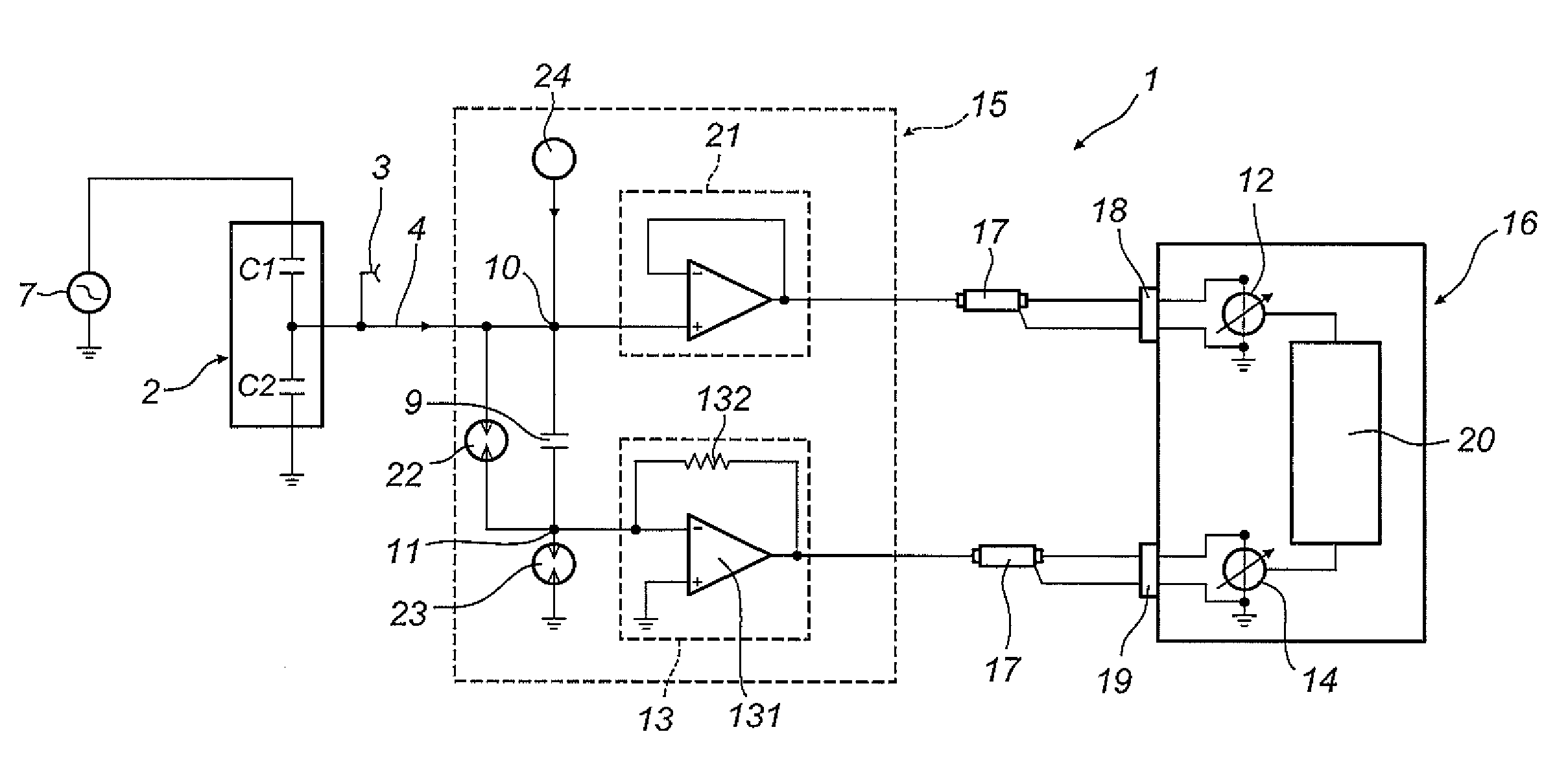
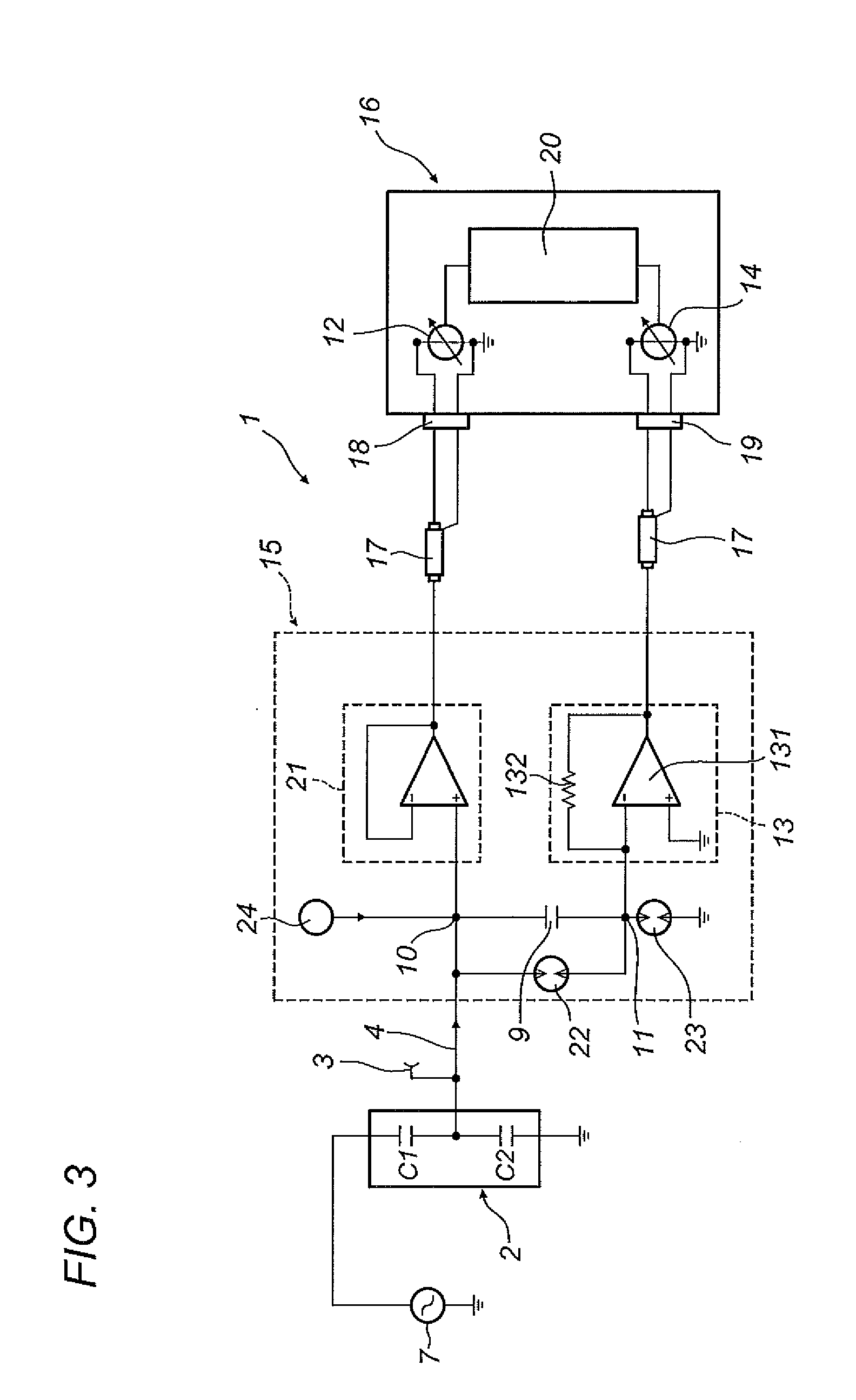
[0065]The numeral 1 in the drawings denotes an apparatus for measuring the loss factor (also known as tan delta, or power factor, or loss tangent) of an insulator 2 for medium or high voltages.

[0066]More specifically, the insulator 2 is an insulator equipped with a tap adapter 3 forming a point for picking up an electrical signal 4.

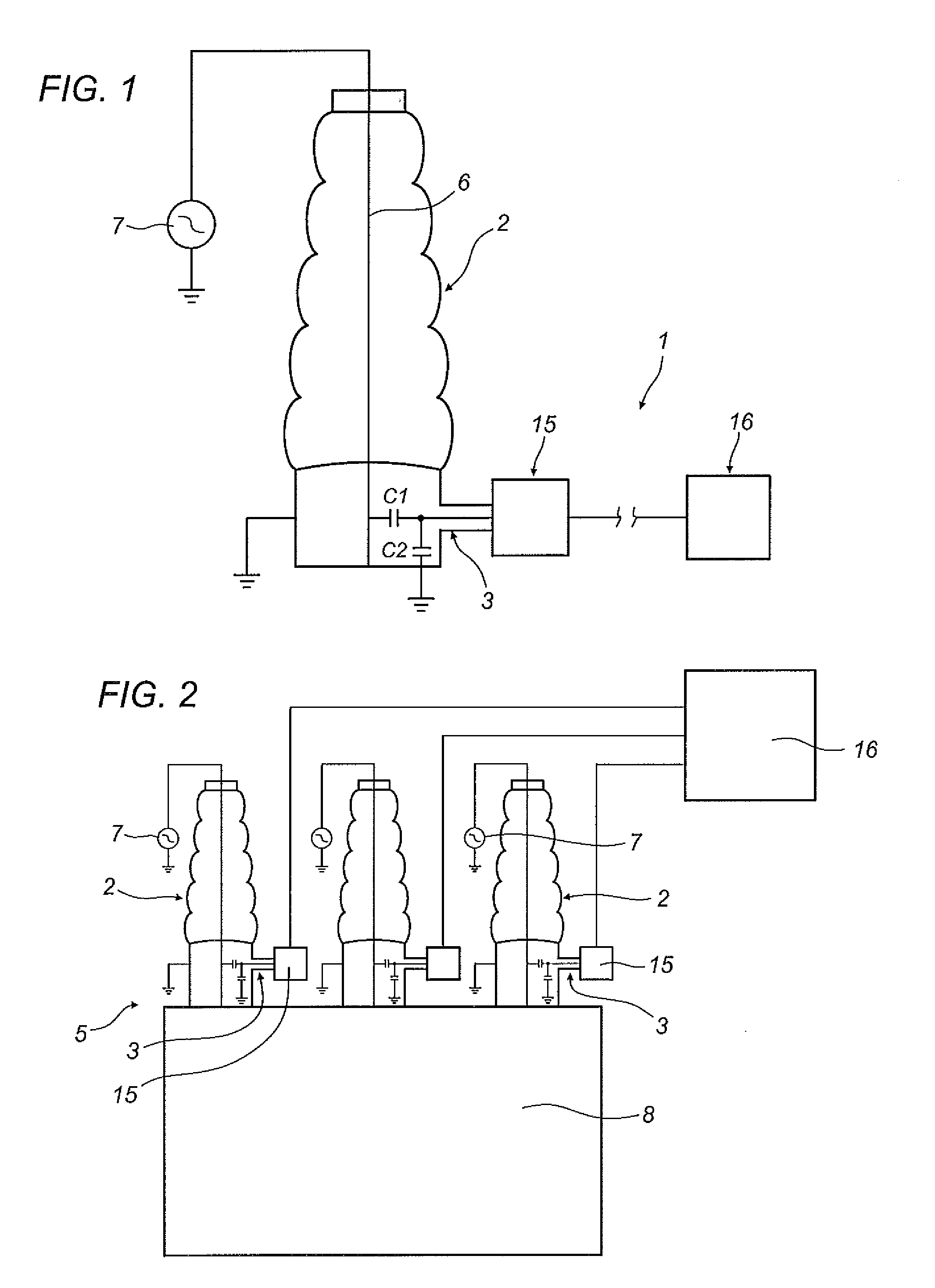
[0067]In a preferred application of this invention, the apparatus 1 is an apparatus for measuring the loss factor of an insulator 2 of a medium- or high-voltage transformer 5.

[0068]FIG. 2 illustrates a three-phase transformer 5 having three medium- or high-voltage insulators 2 the apparatus 1 is coupled to.

[0069]The reference C1 denotes a capacitor corresponding to the insulator 2 being tested, while C2 denotes an eddy capacitor formed by the tap adapter.

[0070]The insulator 2 is designed to insulate a conductor 6 connected to a medium- or high-voltage source 7 relative to a body 8 connected to earth (for example the casing of a transformer).

[0071]The insu...


PUM


Abstract

An apparatus (1) for measuring the loss factor of an insulator (2) for medium or high voltages, equipped with a tap adapter (3) forming a point for picking up an electrical signal (4), comprises: a reference capacitor (9) having a first electrode (10), which can be connected to the tap adapter, and a second electrode (11); a first voltage detection module (12) operatively connected to the first electrode (10) of the reference capacitor (9) for detecting a signal representative of the voltage applied to the reference capacitor (9); an active electronic device (13) connected to earth and to the second electrode (11) of the reference capacitor (9) and configured to keep the potential of the second electrode (11) at a predetermined reference value; a second voltage detection module (14) operatively connected to an output of the active electronic device (13) in order to detect a signal representative of the electric current that flows through the reference capacitor (9).

Description

TECHNICAL FIELD[0001]This invention relates to an instrument and a method for measuring the loss factor of an insulator.[0002]More specifically, this invention relates to an instrument and a method for measuring the loss factor of an insulator (also called bushing) for medium or high voltages, equipped with a tap adapter forming a point for picking up an electrical signal.[0003]More in detail, the invention regards an instrument and a method for measuring the loss factor of an insulator of a medium- or high-voltage transformer, that is to say, an insulator designed to insulate the conductors leading out of the transformer relative to the casing of the transformer itself (or relative to the other conductors in the case of three-phase equipment).[0004]The loss factor—also known as loss angle or tan delta—is a measure of the deviation of the electric behaviour of a real capacitor (or real insulating system) with respect to that of a perfect system.[0005]In effect, the current flowing t...

Claims


Application Information

Patent Timeline
Patent Type & Authority Applications(United States)
IPC IPC(8): G01R27/26H02H1/00H02H3/20
CPCG01R27/2694H02H3/20H02H1/00G01R19/06G01R19/165G01R31/12
Inventor ROLLI, STEFANODE ROBERTIS, GIANPAOLOSERRA, STEFANOMONTANARI, GIAN CARLO
Owner I S A ALTANOVA GRP SRL
Why Eureka
Try Eureka