System and method for improved energy series of images using multi-energy ct

Active Publication Date: 2013-05-02
MAYO FOUND FOR MEDICAL EDUCATION & RES +1
View PDF6 Cites 39 Cited by
  • Summary
  • Abstract
  • Description
  • Claims
  • Application Information

AI Technical Summary

Benefits of technology

[0019]The present invention overcomes the aforementioned drawbacks by providing a system and method for creating an energy series of images acquired using a multi-energy computed tomography (CT) imaging system having a plurality of energy bins. Using the multi-energy CT imaging system, a series of energy data sets is acquired, where each energy data set is associated with at least one of the energy bins. A conglomerate image is produced using a plurality of the energy data sets and, using the conglomerate image, an energy series of images is reconstr

Problems solved by technology

However, unlike in the other scanners, the detectors are not aligned rigidly relative to the x-ray beam.
However, a significant limitation of using narrow bins is that the number of photons available in each energy bin is much smaller than the total number of photons detected.
Thus, a critical problem occurs.
However, this requirement excludes a large percentage of the detected energy spectrum from the considered image data.
Thus, the resultant images, in which dual-energy signal is increased, suffer from increased noise.
For narrow energy bins, especially in the lower energy range, the image noise may be so high as to make it impossible to detect small differences in material composition, that is, the signal to noise ratio (SNR) is too low.
Further, a large portion of the dose delivered to the patient is wasted, creating a difficult dilemma of the clinician balancing between dose delivered and achieving a desired SNR.
Thus, the requirements for increasing dual-energy signal are in direct conflict with the requirements for decreasing image noise in the individual energy images and in any material composition images derived from the energy specific images.
However, the number of photons in each energy bin is only 1/6 of the

Method used


Image

  • System and method for improved energy series of images using multi-energy ct
  • System and method for improved energy series of images using multi-energy ct
  • System and method for improved energy series of images using multi-energy ct

Examples


Embodiment Construction

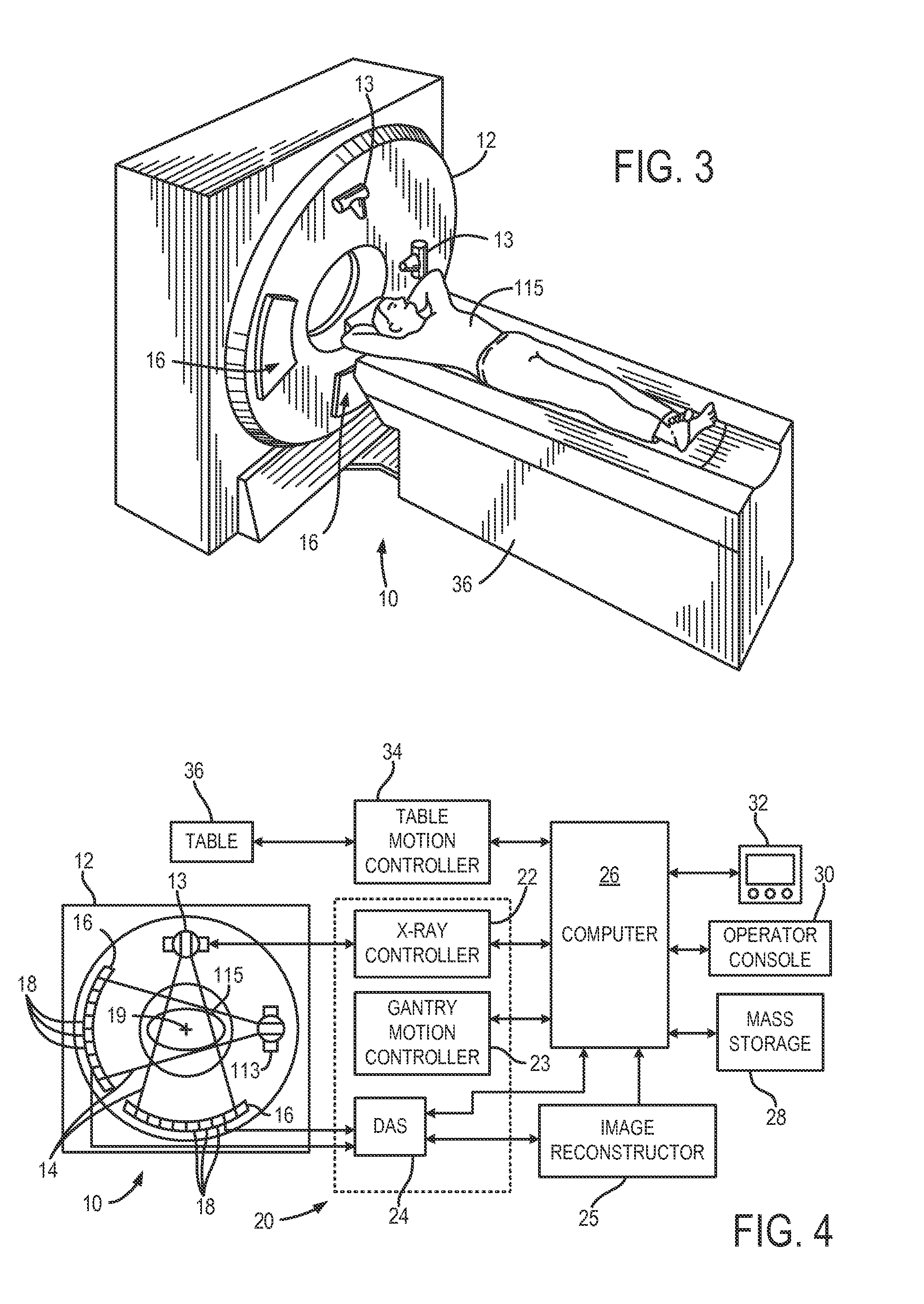
[0033]With initial reference to FIGS. 3 and 4, a computed tomography (CT) imaging system 10 includes a gantry 12 representative of at least a “third generation” CT scanner. In the illustrated example, the gantry 12 has a pair of x-ray sources 13 that each project a fan beam or cone beam of x-rays 14 toward a detector array 16 on the opposite side of the gantry 12. However, it is specifically noted that the present invention, while readily applicable to dual-source, dual-energy CT systems, is also readily applicable to other multi-energy CT systems and methods, such as single-source, dual- or multi-energy CT systems and methods. The detector array 16 is formed by a number of detector elements 18 that together sense the projected x-rays that pass through a medical patient 15. As will be described, it is contemplated that the detector array 16 may form part of a so-called “photon-counting” and / or “energy-discriminating” detector system. In any case, each detector element 18 produces an...


PUM


Abstract

A method for creating an energy series of images acquired using a multi-energy computed tomography (CT) imaging system having a plurality of energy bins includes acquiring, with the multi-energy CT imaging system, a series of energy data sets, where each energy data set is associated with at least one of the energy bins. The method includes producing a conglomerate image using at least a plurality of the energy data sets and, using the conglomerate image, reconstructing an energy series of images, each image in the energy series of images corresponding to at least one of the energy data sets.

Description

CROSS-REFERENCE TO RELATED APPLICATIONS[0001]The present application is based on, claims the benefit of, and incorporates herein by reference U.S. Provisional Application Ser. No. 61 / 365,191, filed Jul. 16, 2010, and entitled, System and Method for Improved Energy Series of Images using Multi-Energy CT.BACKGROUND OF THE INVENTION[0002]The present invention relates to computed tomography (CT) imaging and, more particularly, to systems and methods for energy domain data correction in spectral CT imaging to control noise and radiation dose.[0003]In a computed tomography system, an x-ray source projects a fan or cone shaped beam which is collimated to lie within an X-Y plane of a Cartesian coordinate system, termed the “imaging plane.” The x-ray beam passes through the object being imaged, such as a medical patient or other non-medical patient or object, such as in industrial CT imaging, and impinges upon an array of radiation detectors. The intensity of the transmitted radiation is dep...

Claims


Application Information

Patent Timeline
IPC IPC(8): G06T11/00G01N23/04
CPCA61B6/032A61B6/482A61B6/4241G06T11/003G01N23/046A61B6/50A61B6/5205G01N2223/1016G01N2223/419G01N2223/423G06T5/20
Inventor LENG, SHUAIMCCOLLOUGH, CYNTHIA H.YU, LIFENGFLETCHER, JOEL G.MISTRETTA, CHARLES A.
Owner MAYO FOUND FOR MEDICAL EDUCATION & RES
Why Eureka
Try Eureka