Permanent magnet motor pump

a permanent magnet, canned technology, applied in the direction of piston pumps, positive displacement liquid engines, instruments, etc., can solve the problems of unfavorable detection of accurate magnetic pole positions, increased manufacturing costs, and bearing wear, so as to improve the stiffness of the stationary shaft and the possibility of bearing wear

Active Publication Date: 2013-05-02
ASSOMA
View PDF12 Cites 12 Cited by
  • Summary
  • Abstract
  • Description
  • Claims
  • Application Information

AI Technical Summary

Benefits of technology

[0061](a) simple stationary shaft: the stationary shaft is adapted for general use with full power range and with high possibility of bearing wear; the axially extended blank rear shaft support of the containment shell and the shaft metal rear support shorten the arm length of composite force, and the shaft metal rear support and the blank rear shaft support are tightly combined for improving the stiffness of the stationary shaft; the secondary magnets are installed opposite to the main magnets on the inner sid...

Problems solved by technology

Although the sealless canned motor pump comprises a slide bearing made of ceramic material, the bearing may be worn because of the bearing wear, dry-running or excessive vibration.
The simple stationary structure is adopted but the addition of the length of the magnets may increase the manufacturing cost, and only the magnetic flux which is scattered on a surface of the magnets are detected, it is unfavorable for detecting accurate magnetic pole position.
When an axial wear happens on one side of a bearing, the radial position of the plate is moved in a radial direction, which causes the plate close to or away from the coil set.
However, when repairing a motor, including replacing a stator, a inner rotor...

Method used


Image

  • Permanent magnet motor pump
  • Permanent magnet motor pump
  • Permanent magnet motor pump

Examples


first embodiment

The Canned Pump Including a Doubled-Sided-Supported Stationary Shaft without any Monitor Device as Shown in FIGS. 1A and 3A

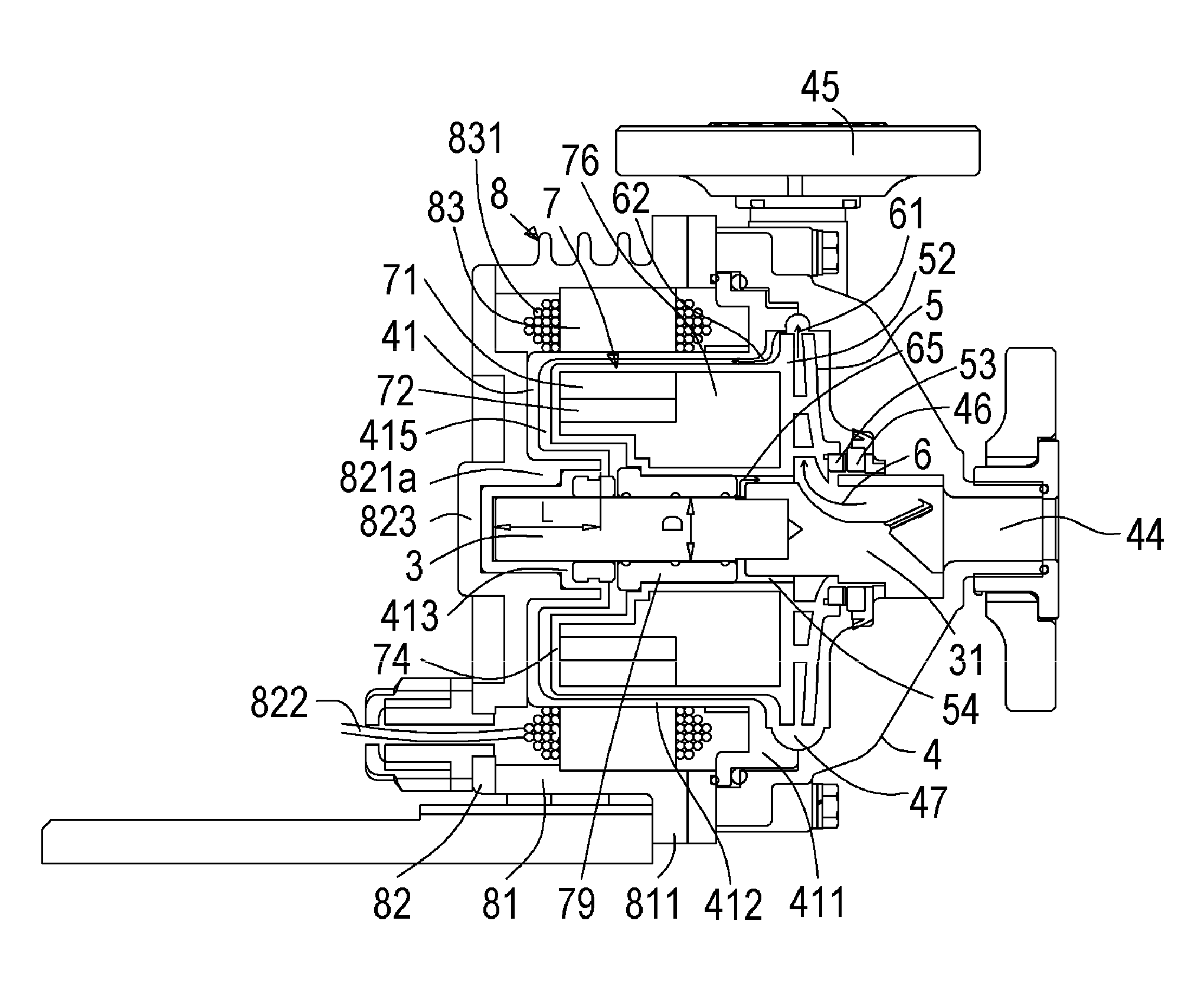
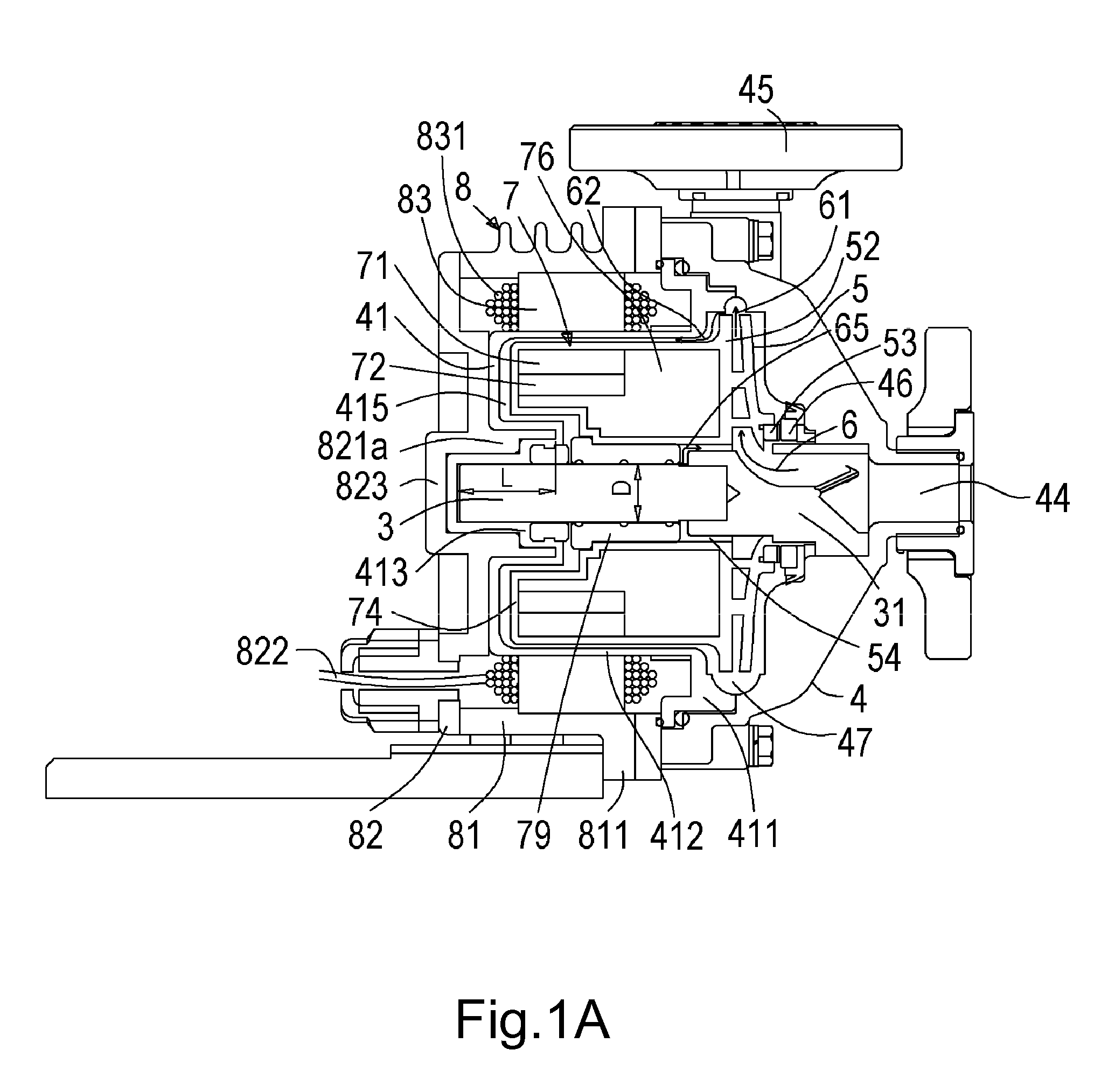
[0084]With reference to FIG. 1A, 3A, FIG. 1A is a cross-sectional view of a double-sided-supported stationary shaft without any monitor device of the canned pump according to the present invention, and FIG. 3A is a cross-sectional view of a containment shell of a double-sided-supported stationary shaft of the canned pump according to the present invention. The canned pump comprises: a pump casing 4, a triangle front support 31, a type I impeller 5, a type I containment shell 41, a stationary shaft 3 and a canned motor 8.

[0085]The pump casing 4 includes an inlet 44, an outlet 45 and a flow channel 47, and is used for containing the type I impeller 5. A front thrust ring 46, installed on an inner side of the inlet 44 of the pump casing 4, is used for mating with a thrust bearing 53 of the type I impeller 5 to form an axial thrust bearing together.

[0086]The triangl...

second embodiment

The Canned Pump Including a Singled-Sided-Supported Cantilever Composited Stationary Shaft without any Monitor Device which is Shown as in FIG. 1C, FIG. 3B and FIG. 5B

[0096]With reference to FIG. 1C and FIG. 3B, FIG. 1Ac is a cross-sectional view of a single-sided-supported cantilever composited stationary shaft without any monitor device of the canned pump according to the present invention, FIG. 3B is a cross-sectional view of a containment shell of a cantilever stationary shaft of the canned pump according to the present invention, and FIG. 5B shows an inner rotor bearing multiple forces and moments thereof on a single-sided-supported cantilever stationary shaft according to the present invention. The canned pump comprises a metal casing 4a, a type II impeller 5a, a type II containment shell 41a, a composited stationary shaft 3a and a canned motor 8.

[0097]The metal casing 4a which includes an inlet 44, an outlet 45 and a flow channel 47 is used for containing the type II impeller...

third embodiment

The Canned Pump Including a Doubled-Sided-Supported Cantilever Composited Stationary Shaft and a Monitor Device Shown in FIGS. 1B, 1E and FIG. 3A

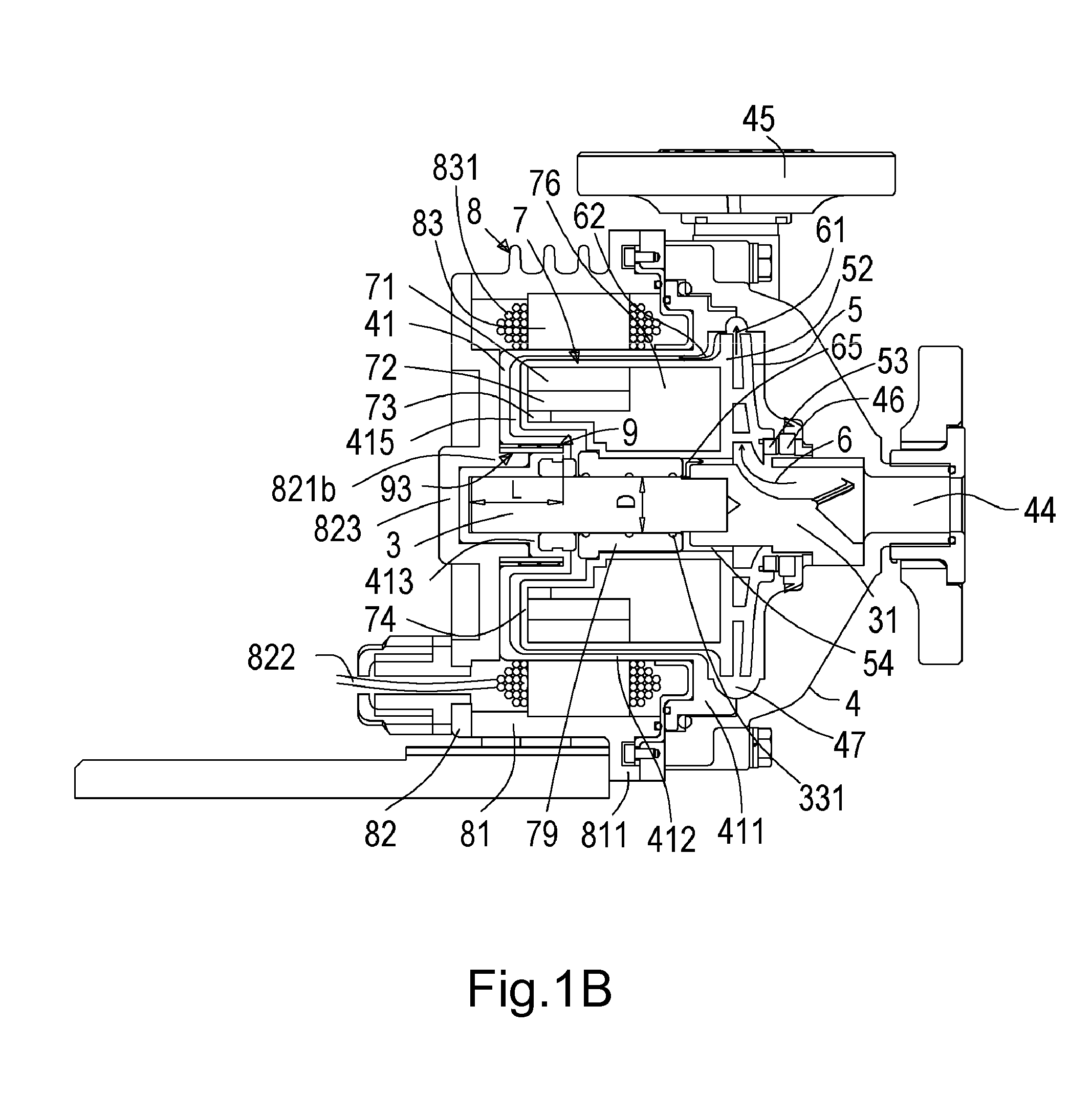
[0107]With reference to FIG. 1B, 1E and FIG. 3A, FIG. 1B is a cross-sectional view of a double-sided supported stationary shaft with a monitor device of the canned pump according to the present invention, FIG. 1E is a cross-sectional view of a double-sided-supported stationary shaft with a monitor device and with a lengthened bearing of the canned pump according to the present invention, and FIG. 3A is a cross-sectional view of a containment shell of a double-sided-supported stationary shaft of the canned pump according to the present invention. The canned pump comprises a pump casing 4, a triangle front support 31, a type I impeller 5, a type I containment shell 41, a monitor device 9, a stationary shaft 3 and a canned motor 8.

[0108]The pump casing 4 includes an inlet 44, an outlet 45 and a flow channel 47, and is used for containing the t...


PUM


Abstract

A structural improvement of the canned pump is to improve the stiffness of a stationary shaft and, according to requirement, to dispose a monitor device. The method for improving the stiffness of the stationary shaft includes axially inserting a shaft metal rear support of the metal structural of a motor rear casing of a canned motor into the inner side of a rotor yoke of an inner rotor of the canned motor, tightly attaching the shaft metal rear support to a rear shaft seat for improving the stiffness of the stationary shaft by longer hold length, and for shortening an arm length of the composite force. The monitor device, used for detecting the wear of a bearing for enhancing the reliability and satisfying the driving requirement, is installed in the ring slot to be protected by the rear shaft seat.

Description

CROSS-REFERENCE TO RELATED APPLICATIONS[0001]This non-provisional application claims priority under 35 U.S.C. §119(a) on Patent Application No(s). 100138846 filed in Taiwan, R.O.C. on Oct. 26, 2011, the entire contents of which are hereby incorporated by reference.BACKGROUND OF THE INVENTION[0002]1. Technical Field[0003]The invention relates to a sealless canned motor pump, more particularly to, an anti-corrosion and sealless canned motor pump including a bearing monitor device. The sealless canned motor pump comprises a canned motor and a pump integrated into one unit. An inner rotor and a stator windings of the motor are protected by an anti-corrosion material and are in direct contact with transferred fluid, such as chemical liquid in the PCB manufacturing device, is toxic, flammable and corrosive. The motor, including an induction motor (induction canned motor pump) or a permanent magnet pump (permanent magnet canned motor pump), are popular among industrial use requiring leakag...

Claims


Application Information

Patent Timeline
IPC IPC(8): F04D13/06
CPCF04D13/0626H02K5/1677F04D29/0465F04D13/0633F04D7/06F04D15/0094F05B2240/14F05B2240/52F05B2280/4003F04D29/40F04D13/06G01R33/07G01R33/077F04B49/065F04B2207/70F04C2270/78G01M13/04H02K11/20F04D29/046F04D13/026H02K11/215F04D29/22F04D15/0088F04D29/4286
Inventor CHIEN, HUAN-JANWANG, CHIN-CHENGSHIH, CHIH-HSIEN
Owner ASSOMA
Why Eureka
Try Eureka