Unlock instant, AI-driven research and patent intelligence for your innovation.

Golf club assembly and golf club with aerodynamic features

a golf club and aerodynamic technology, applied in the field of golf clubs and golf club heads with aerodynamic features, can solve the problems of increasing the drag during other phases of the swing cycle, causing pressure drag, and affecting the swing path of the golf club head, so as to improve the aerodynamic performance and reduce the drag

Inactive Publication Date: 2013-05-02
NIKE INC
View PDF4 Cites 2 Cited by
  • Summary
  • Abstract
  • Description
  • Claims
  • Application Information

AI Technical Summary

Benefits of technology

The patent text describes a golf club head with improved aerodynamic performance. A drag reducing structure is designed to reduce drag during the downstroke of the swing, when the velocity of the golf club head is nearing or at its maximum. This helps to create a more stable and accurate swing.

Problems solved by technology

The club head of a driver or a fairway wood in particular produces significant aerodynamic drag during its swing path.
This low pressure separation region creates pressure drag.
Club heads that have been designed to reduce the drag of the head at the point of impact, or from the point of view of the club face leading the swing, may actually increase the drag during other phases of the swing cycle, such as when the heel / hosel region of the club head is leading the downswing.

Method used


Image

  • Golf club assembly and golf club with aerodynamic features
  • Golf club assembly and golf club with aerodynamic features
  • Golf club assembly and golf club with aerodynamic features

Examples


Embodiment Construction

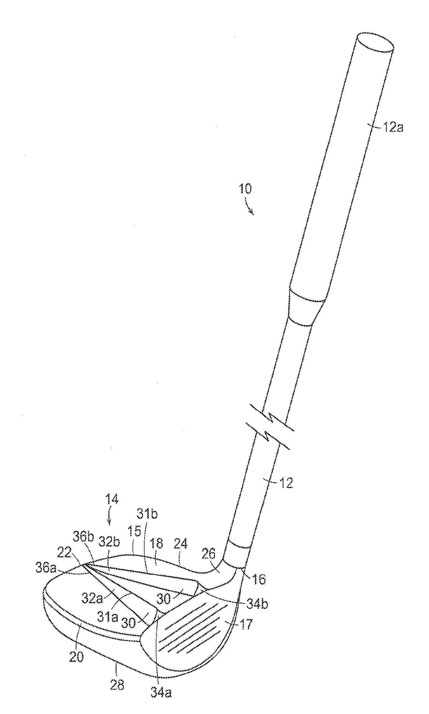
[0028]An illustrative embodiment of a golf club 10 is shown in FIGS. 1A through 3. As best shown in FIG. 1A, golf club 10 includes a shaft 12 and a golf club head 14 attached to the shaft 12. Golf club head 14 may be any driver, wood, or the like. The shaft 12 of the golf club 10 may be made of various materials, such as steel, aluminum, titanium, graphite, or composite materials, as well as alloys and / or combinations thereof, including materials that are conventionally known and used in the art. Additionally, the shaft 12 may be attached to the club head 14 in any desired manner, including in conventional manners known and used in the art (e.g., via adhesives or cements at a hosel element, via fusing techniques (e.g., welding, brazing, soldering, etc.), via threads or other mechanical connectors (including releasable and adjustable connections), via friction fits, via retaining element structures, etc.). A grip or other handle element 12a is positioned on the shaft 12 to provide a ...


PUM


Abstract

A golf club head has a body member that includes a ball striking face, a crown region, a toe region, a heel region, a sole region, a rear region and a hosel region. The body member has a drag-reduction feature that may include first and second elongated fins. The fins extend in a generally front-to-rear orientation. The fins are spaced farther apart at their forward-most ends than at their rearward-most ends. Alternatively, the drag-reduction feature may include first and second elongated indentations. The indentations extend in a generally front-to-rear orientation. The indentations are spaced farther apart at their forward-most ends than at their rearward-most ends. The drag-reduction features may be located on one or both of the crown region or the sole region. A golf club including the golf club head is also provided.

Description

RELATED CASES[0001]This application is a divisional application of, and claims priority to, pending U.S. patent application Ser. No. 12 / 754,772, filed on Apr. 6, 2010, by Jeremy Snyder, and titled “Golf Club Assembly and Golf Club with Aerodynamic Features,” which is entirely incorporated herein by reference.FIELD[0002]Aspects of this invention relate generally to golf clubs and golf club heads, and, in particular, to golf clubs and golf club heads with aerodynamic features.BACKGROUND[0003]The distance a golf ball travels when struck by a golf club is determined in large part by club head speed at the point of impact with the golf ball. Club head speed in turn can be affected by the wind resistance or drag provided by the club head during the entirety of the swing, especially given the large club head size of a driver. The club head of a driver or a fairway wood in particular produces significant aerodynamic drag during its swing path. The drag produced by the club head leads to red...

Claims


Application Information

Patent Timeline
IPC IPC(8): A63B53/04
CPCA63B53/0466A63B2053/0433A63B2053/0437A63B53/04A63B2053/0408A63B2225/01A63B53/0408A63B53/0437A63B53/0433A63B60/006A63B60/00
Inventor SNYDER, JEREMY N
Owner NIKE INC