Resin composition for laser engraving, relief printing plate precursor for laser engraving and process for producing same, and relief printing plate and process for making same

a technology of laser engraving and resin composition, which is applied in the direction of foil printing, transportation and packaging, nuclear engineering, etc., can solve the problems of difficult production and inability to obtain desired film physical properties such as film toughness

Inactive Publication Date: 2013-05-09
FUJIFILM CORP
View PDF3 Cites 0 Cited by
  • Summary
  • Abstract
  • Description
  • Claims
  • Application Information

AI Technical Summary

Benefits of technology

[0017]Due to the resin composition for laser engraving of the present invention comprising Component A, phase separation of a polymer formed in a film is suppressed, and a film having excellent compositional uniformity and toughness and a relief printing plate having little breakage of small-size halftone dots can be obtained.

Problems solved by technology

The flexographic plate precursor is given desired physical properties by thermal curing or photocuring, but it is difficult to produce, by photocuring, a flexographic plate precursor that can carry out photothermal conversion of visible and near-infrared light lasers, and as a solution for this a method for producing a laser engraving type flexographic plate precursor by thermal crosslinking has been disclosed (JP-A-2008-63553 (JP-A denotes a Japanese unexamined patent application publication)).
Thermal curing or photocuring of a relief-forming layer of the relief printing plate precursor utilizes a crosslinking reaction or a chain transfer polymerization reaction of a binder, but it has become clear that desired film physical properties such as film toughness cannot be obtained due to phase separation of a polymer formed in the film.

Method used


Image

  • Resin composition for laser engraving, relief printing plate precursor for laser engraving and process for producing same, and relief printing plate and process for making same
  • Resin composition for laser engraving, relief printing plate precursor for laser engraving and process for producing same, and relief printing plate and process for making same
  • Resin composition for laser engraving, relief printing plate precursor for laser engraving and process for producing same, and relief printing plate and process for making same

Examples


example 1

Preparation of Relief Printing Plate Precursor for Laser Engraving

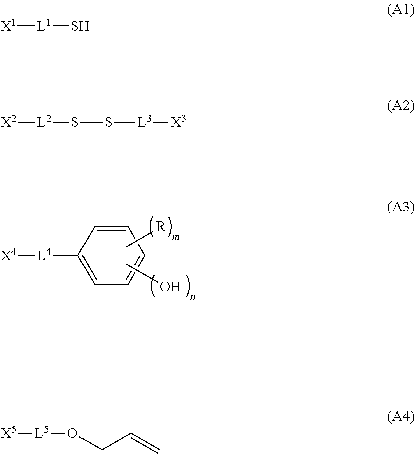
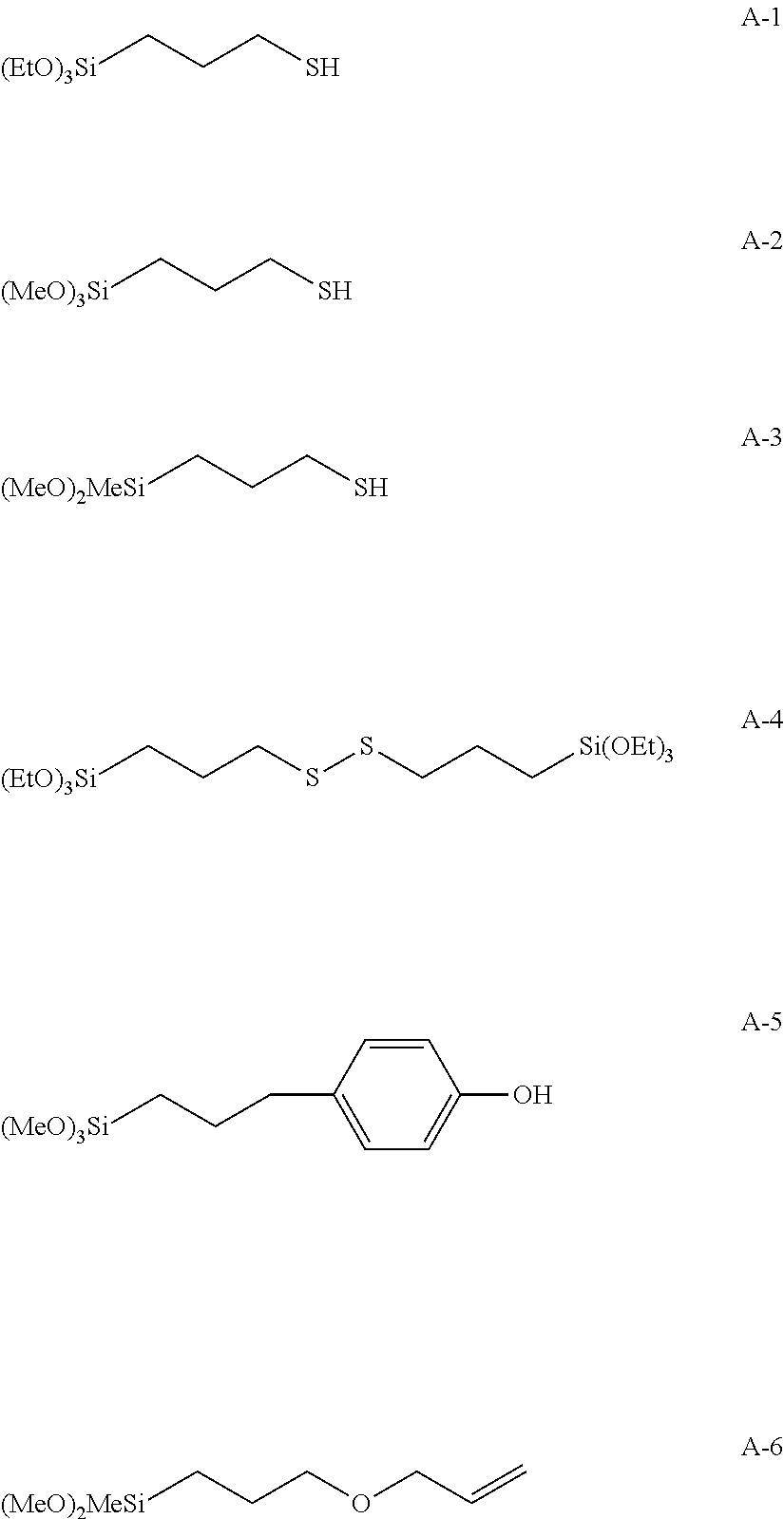
[0288](Component A) the compound shown in Table 1, (Component B) the radically polymerizable compound, (Component D) the resin, and the materials shown below were mixed. The solids content concentrations of Component A, Component B, and Component D are shown in Table 1. Materials other than Component A, Component B, and Component D were mixed at the proportions below.

(Component A) compound shown in Table 1: parts by weight shown in Table 1

(Component B) radically polymerizable compound: parts by weight shown in Table 1

(Component D) resin: parts by weight shown in Table 1

Bisbutoxyethyl adipate: 25 parts by weight

Carbon black: 4 parts by weight

DBU (condensation reaction catalyst): 1 part by weight

Propylene glycol monomethyl ether acetate (solvent): 20 parts by weight

[0289]A three-necked flask equipped with a stirring blade and a condenser was charged with the components above, and they were dissolved by heating at 70° C....


PUM

PropertyMeasurementUnit
thicknessaaaaaaaaaa
thicknessaaaaaaaaaa
temperatureaaaaaaaaaa

Abstract

To provide a resin composition for laser engraving that can give a film having excellent compositional uniformity and toughness and a relief printing plate having little breakage of small-size halftone dots, a relief printing plate precursor employing the resin composition for laser engraving, a process for making a relief printing plate employing same, and a relief printing plate obtained thereby.A resin composition for laser engraving of the present invention that includes (Component A) a compound having one or more condensable groups and having one or more radical chain transfer groups; (Component B) a radically polymerizable compound; (Component C) a radical polymerization initiator; and (Component D) a binder polymer.

Description

TECHNICAL FIELD[0001]The present invention relates to a resin composition for laser engraving, a relief printing plate precursor for laser engraving and a process for producing the same, and a relief printing plate and a process for making the same.BACKGROUND ART[0002]A large number of so-called “direct engraving CTP methods”, in which a relief-forming layer is directly engraved by means of a laser are proposed. In the method, a laser light is directly irradiated to a flexographic printing plate precursor to cause thermal decomposition and volatilization by photothermal conversion, thereby forming a concave part. Differing from a relief formation using an original image film, the direct engraving CTP method can control freely relief shapes. Consequently, when such image as an outline character is to be formed, it is also possible to engrave that region deeper than other regions, or, in the case of a fine halftone dot image, it is possible, taking into consideration resistance to pri...

Claims


Application Information

Patent Timeline
Patent Type & Authority Applications(United States)
IPC IPC(8): C08L37/00
CPCB41N1/12B41C1/05
Inventor YAMASHITA, KATSUHIRO
Owner FUJIFILM CORP
Why Eureka
Try Eureka