Method for operating an internal combustion engine
- Summary
- Abstract
- Description
- Claims
- Application Information
AI Technical Summary
Benefits of technology
Problems solved by technology
Method used
Image
Examples
Embodiment Construction
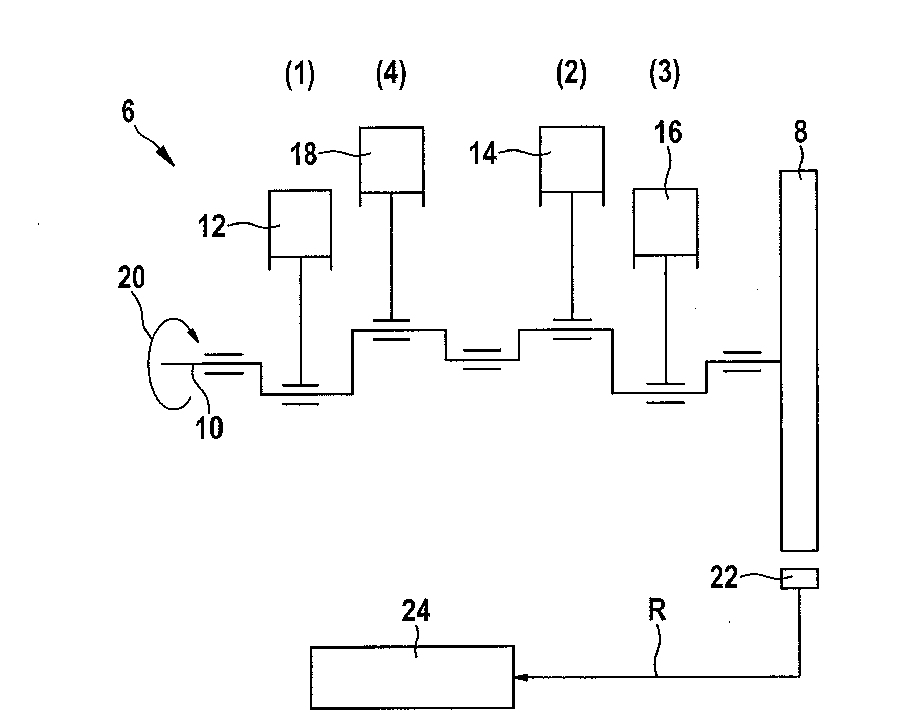
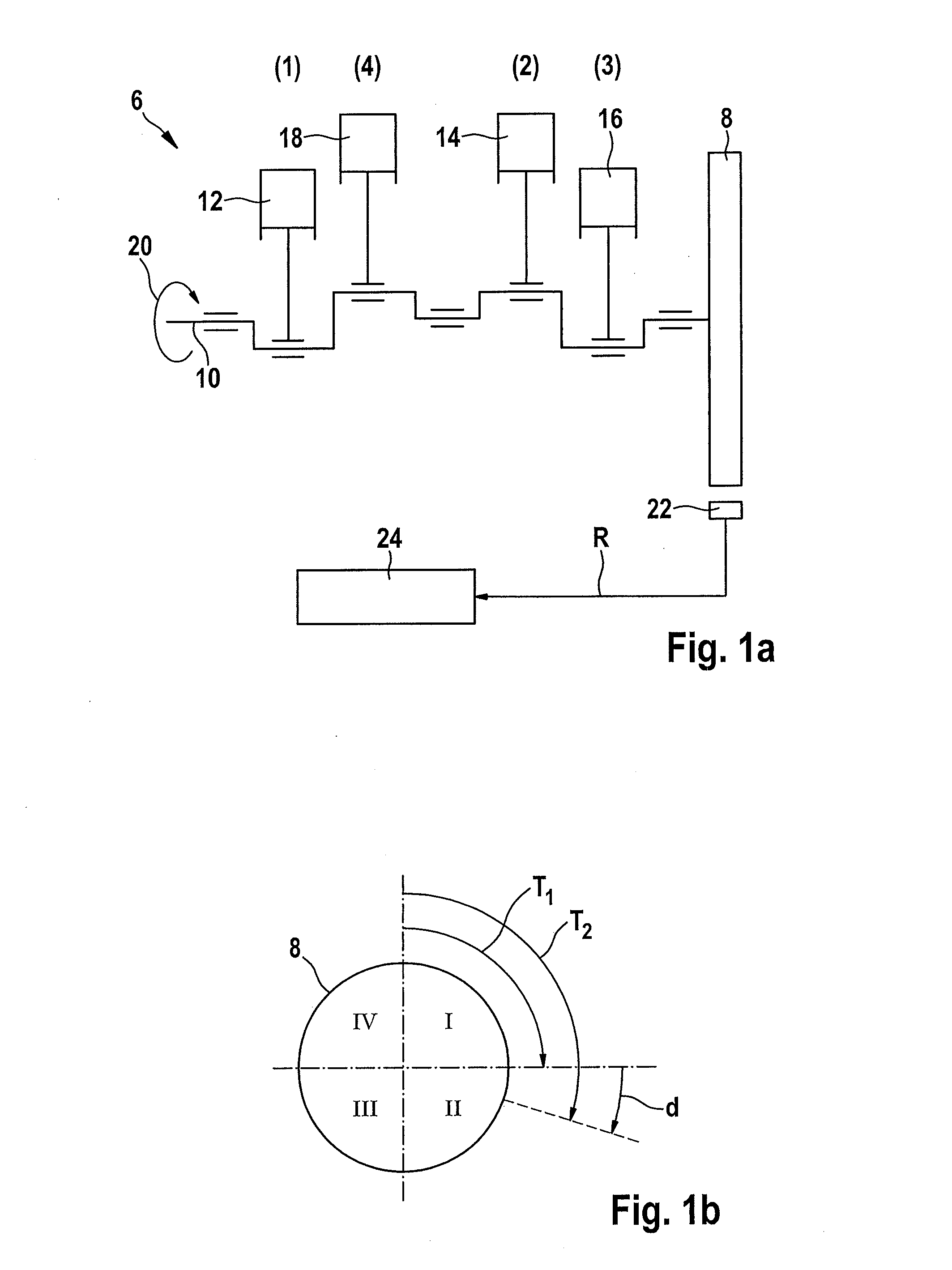
[0031]FIG. 1a shows a schematically illustrated internal combustion engine 6 having a sensor wheel 8, sensor wheel 8 being shown in a lateral view. Internal combustion engine 6 includes a crankshaft 10 having pistons 12, 14, 16, and 18 installed at crankshaft 10. Pistons 12, 14, 16, and 18 are each assigned to a cylinder which is identified by 1, 2, 3, and 4 according to the ignition sequence of internal combustion engine 6. Crankshaft 10 rotates in a direction of rotation 20. The number of cylinders is identified by n, n=4 in the present example. A certain cylinder is identified by i, i=1, 2, 3, 4 in the present example.
[0032]Sensor wheel 8 is fixedly connected to crankshaft 10. Sensor wheel 8 includes a tooth pattern which is situated along the periphery of sensor wheel 8. A crankshaft sensor 22 detects the angular position of crankshaft 10 via the tooth pattern of sensor wheel 8. According to the angular position of sensor wheel 8, crankshaft sensor 22 generates a crankshaft sign...
PUM
 Abstract
Description
Claims
Application Information
 - R&D
- Intellectual Property
- Life Sciences
- Materials
- Tech Scout
- Unparalleled Data Quality
- Higher Quality Content
- 60% Fewer Hallucinations
Browse by: Latest US Patents, China's latest patents, Technical Efficacy Thesaurus, Application Domain, Technology Topic, Popular Technical Reports.
© 2025 PatSnap. All rights reserved.Legal|Privacy policy|Modern Slavery Act Transparency Statement|Sitemap|About US| Contact US: help@patsnap.com


