
Rotor of permanent magnet synchronous motor, motor and machine tool

a synchronous motor and permanent magnet technology, applied in the direction of dynamo-electric machines, magnetic circuit rotating parts, magnetic circuit shape/form/construction, etc., can solve the problems of low rigidity of the main shaft, affecting the dimensional precision, surface roughness and appearance of the workpiece, and the stress as a whole tends to increase on the side of the rotary sha

Active Publication Date: 2013-05-16
FANUC LTD
View PDF5 Cites 14 Cited by
  • Summary
  • Abstract
  • Description
  • Claims
  • Application Information

AI Technical Summary

Benefits of technology

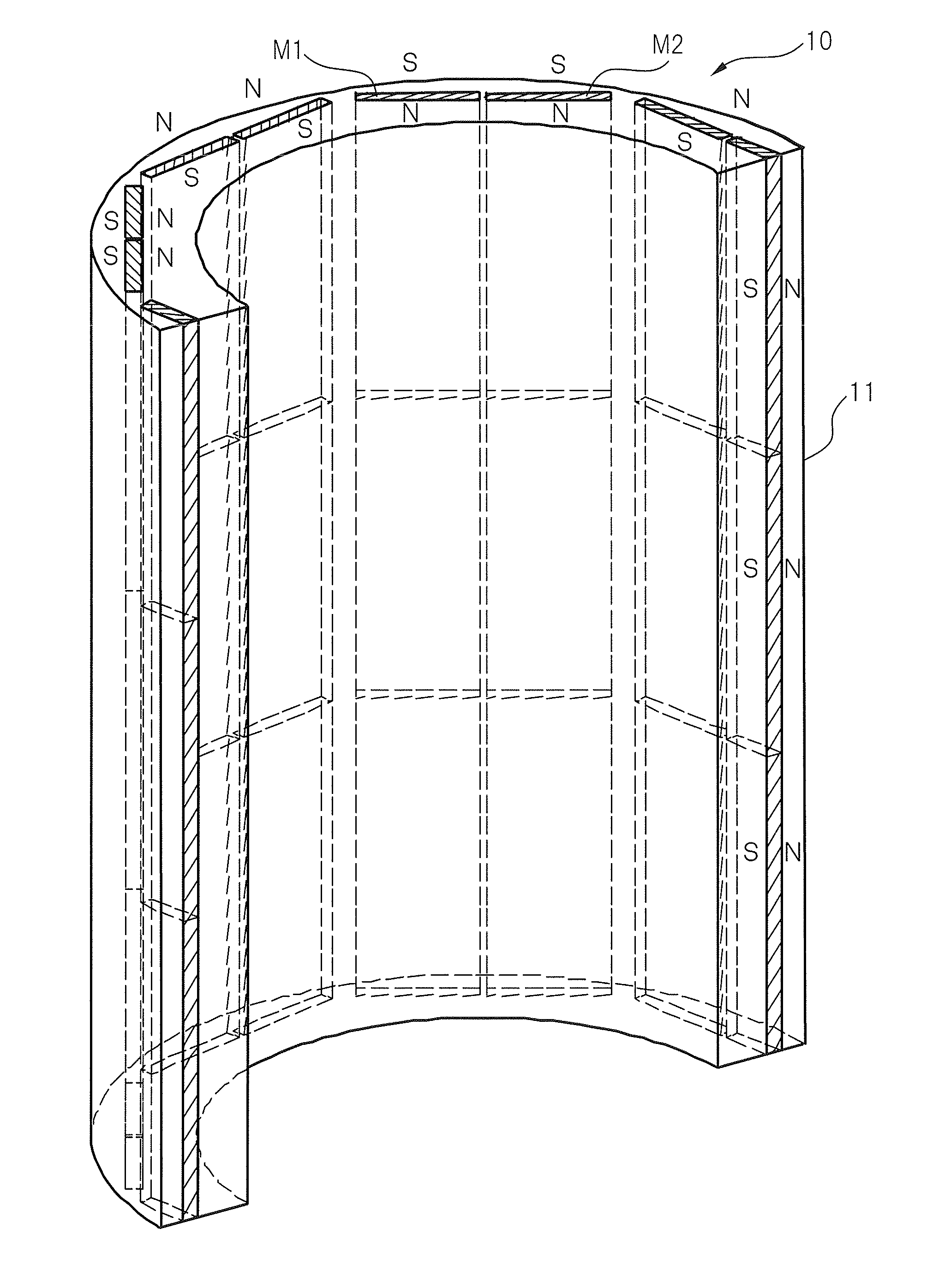
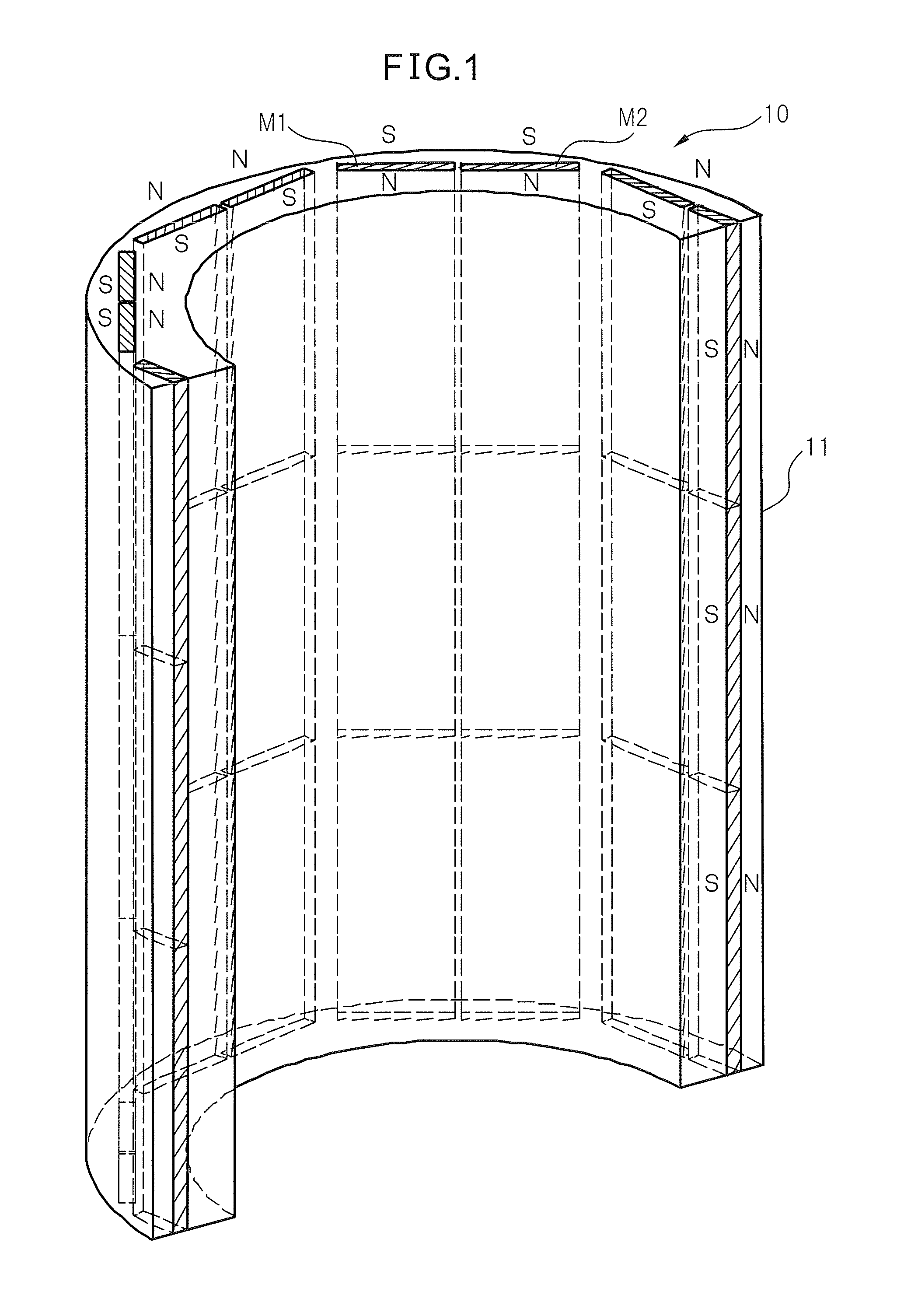
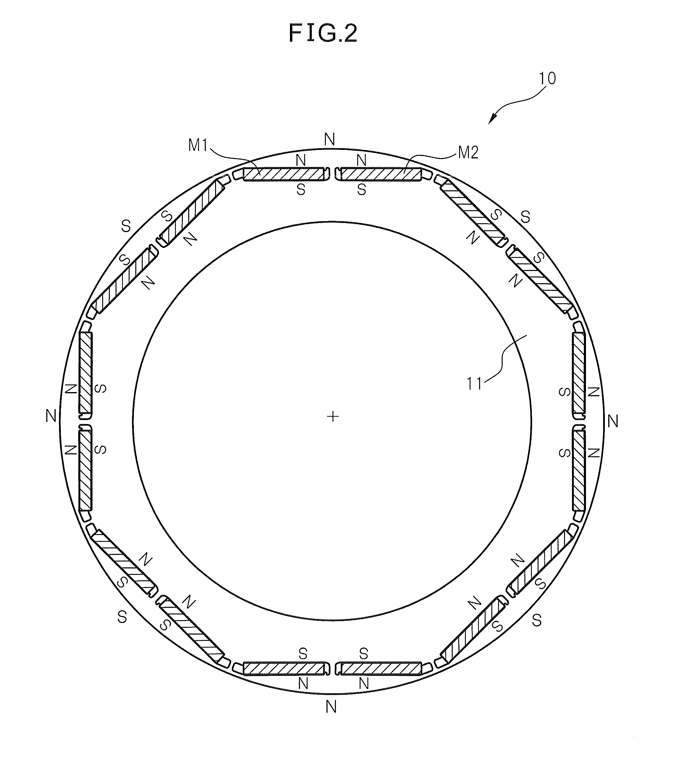
This patent describes a rotor design for electric motors that allows for faster rotating speeds while maintaining high levels of machining precision. The rotor includes a core portion with narrow and wide portions between the magnet slots, which help to reduce leakage flux and enhance torque generation. The electric motor mounts on a machine tool's main shaft, which allows for higher speeds without compromising rigidity. Additionally, the design reduces the likelihood of short-circuiting the magnets and increases the inner diameter of the rotor while decreasing local demagnetizing field. The rotor also includes aspects related to decreasing magnetic flux that may short-circuit the magnets and utilizing curved edges.

Problems solved by technology

For example the main shaft having a low rigidity undergoes vibration affecting the dimensional precision, surface roughness and appearance of the workpiece that is machined.
This is attributed to low performance of the main shaft.
Therefore, the shape disclosed in Japanese Unexamined Patent Publication No. 2002-281700 is disadvantageous when a large inner diameter is required.
However, in the case of the rotor having a large inner diameter, a particularly increased force is exerted on the core portion of the magnet slots on the side of the rotary shaft, and the stress as a whole tends to increase in the core portion on the side of the rotary shaft.

Method used


Image

  • Rotor of permanent magnet synchronous motor, motor and machine tool
  • Rotor of permanent magnet synchronous motor, motor and machine tool
  • Rotor of permanent magnet synchronous motor, motor and machine tool

Examples


first embodiment

[0084]FIG. 5 is a view illustrating the invention. In FIG. 5, two arcs of different sizes are forming the curved portion 41. The curved portion 41 formed of the two arcs assumes a simple shape, produces the above-mentioned effect to a large extent and provides practicability to a high degree. Further, specifically preferred state of connection include such relations as two arcs are connected to each other, an arc is connected to the lower edge 31a of the magnet slot 31, and the arc is connected to the outer edge of the core portion 12 between the magnet slots of the same pole.

[0085]As can be seen from FIG. 5, the bottom edge 31a of the magnet slot 31 is a tangential line of a first arc of R2.8 (radius of 2.8 mm, hereinafter the same). Then, the first arc of R2.8 is connected to a second arc of R0.8. In other words, the center of the second arc of R0.8 is present on a line of radius R2.8 that passes through a point of connection of the first arc and the second arc. In FIG. 5, further...

second embodiment

[0086]FIG. 6 is a view illustrating the invention. In FIG. 6, a curve is formed by the outer edge of the core portion 12 between the magnet slots of the same pole. A first arc of R2.8 connects to the bottom edge 31a of the magnet slot 31, a second arc of R0.8 connects to the first arc and, further, an arc of R5 connects to the second arc, the arcs forming the outer edge of the core portion 12 between the magnet slots of the same pole.

third embodiment

[0087]FIG. 7 is a view illustrating the invention. FIG. 7 shows another curved portion 41 of which the curvature is gradually increasing from the bottom edge 31a up to the outer edge of the core portion 12 between the magnet slots of the same pole. The curved portion 41 shown in FIG. 7 is corresponding to a quarter of an ellipse that has a long axis of 3.2 mm and a short axis of 1.8 mm. As can be seen from FIG. 7, the bottom edge 31a of the magnet slot 31 and the linear outer edge of the core portion 12 between the magnet slots of the same pole are serving as tangential lines to the quarter of the ellipse.

[0088]If a change in the curvature of the embodiment of FIG. 7 is regarded as a gradient of the tangential line, the gradient of the tangential line is 0° at a point of connection to the bottom edge 31a of the magnet slot 31. Then, the gradient of the tangential line monotonously increases toward the outer edge of the core portion 12 between the magnet slots of the same pole. The g...


PUM


Abstract

A rotor (10) of a buried magnet-type electric motor, wherein the magnetic poles thereof are each constituted by two rows of magnets (M1, M2) of the same pole, wherein a core portion (12) between magnet slots of the same pole is arranged between the magnet slots (31, 32) in which the two rows of magnets are arranged, and wherein, of the edges constituting said magnet slots, the portions connecting the edges (31a, 32a) on the inner side in the radial direction to the outer edges of the core portion between the magnet slots of the same pole, have curved portions (41, 42) that connect a curve of a small curvature to a curve of a large curvature starting from the edges on the inner side in the radial direction and heading toward the outer edges of the core portion between the magnet slots of the same pole.

Description

BACKGROUND OF THE INVENTION[0001]1. Field of the Invention[0002]This invention relates to a rotor of a buried magnet-type permanent magnet synchronous rotary electric motor. The invention, further, relates to a motor mounting the above rotor and to a machine tool mounting the above motor.[0003]2. Description of the Related Art[0004]A buried magnet-type synchronous motor has been widely used. Such a motor is a built-in motor which is directly incorporated in, for example, a main shaft of a machine tool to directly drive the main shaft, and is required to have a relatively large inner diameter and to rotate at a high speed.[0005]The rotor of the built-in motor is fixed to the outer diameter portion of the main shaft, usually, by shrinkage fit. Therefore, the inner diameter of the rotor of the built-in motor is required to be nearly the same as the outer diameter of the main shaft.[0006]Depending upon the dimensional precision and surface roughness of a workpiece that is to be machined...

Claims


Application Information

Patent Timeline
Patent Type & Authority Applications(United States)
IPC IPC(8): H02K1/27
CPCH02K2213/03H02K1/276
Inventor ARIMATSU, YOHEIKAWAI, KENJI
Owner FANUC LTD
Learn More