
Liquid ejection apparatus and drive method for inkjet head

Inactive Publication Date: 2013-05-16
FUJIFILM CORP +1
View PDF1 Cites 1 Cited by
  • Summary
  • Abstract
  • Description
  • Claims
  • Application Information

AI Technical Summary

Benefits of technology

The invention provides a liquid ejection apparatus and a drive method for the inkjet head that can prevent the piezoelectric element from breaking when a voltage is applied. This results in a thinner piezoelectric element film thickness.

Problems solved by technology

Here, it is known that piezoelectric elements have a large number of defects, such as small cracks or voids, and the like.
When an electric field of high intensity is applied to a piezoelectric element containing lead under conditions where water (moisture) is present, large electric current flows through the lead compound in the defective portion and the peripheral area thereof, and the location where the large electric current occurs is destroyed by Joule heat and hence creates a larger defect.
By forming the piezoelectric element with a large thickness, it is possible to avoid the occurrence of large defects which pass through the element due to the breakage; however, it becomes necessary to apply an electric field of high intensity to the piezoelectric element in order to obtain a desired pressure applied to the liquid in the liquid chamber, and hence there are concerns about increase in the electric power consumption.
Moreover, if the atmosphere around the piezoelectric element is of high humidity before starting the supply of the dried air, then there is a problem of breakage of the piezoelectric element occurring the moment a voltage is applied to the piezoelectric element.

Method used


Image

  • Liquid ejection apparatus and drive method for inkjet head
  • Liquid ejection apparatus and drive method for inkjet head
  • Liquid ejection apparatus and drive method for inkjet head

Examples


Embodiment Construction

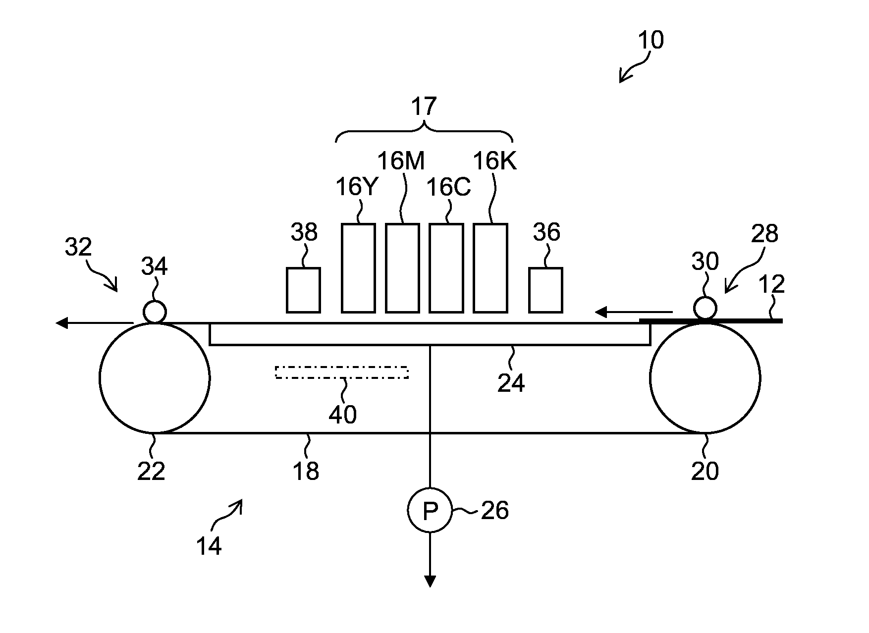
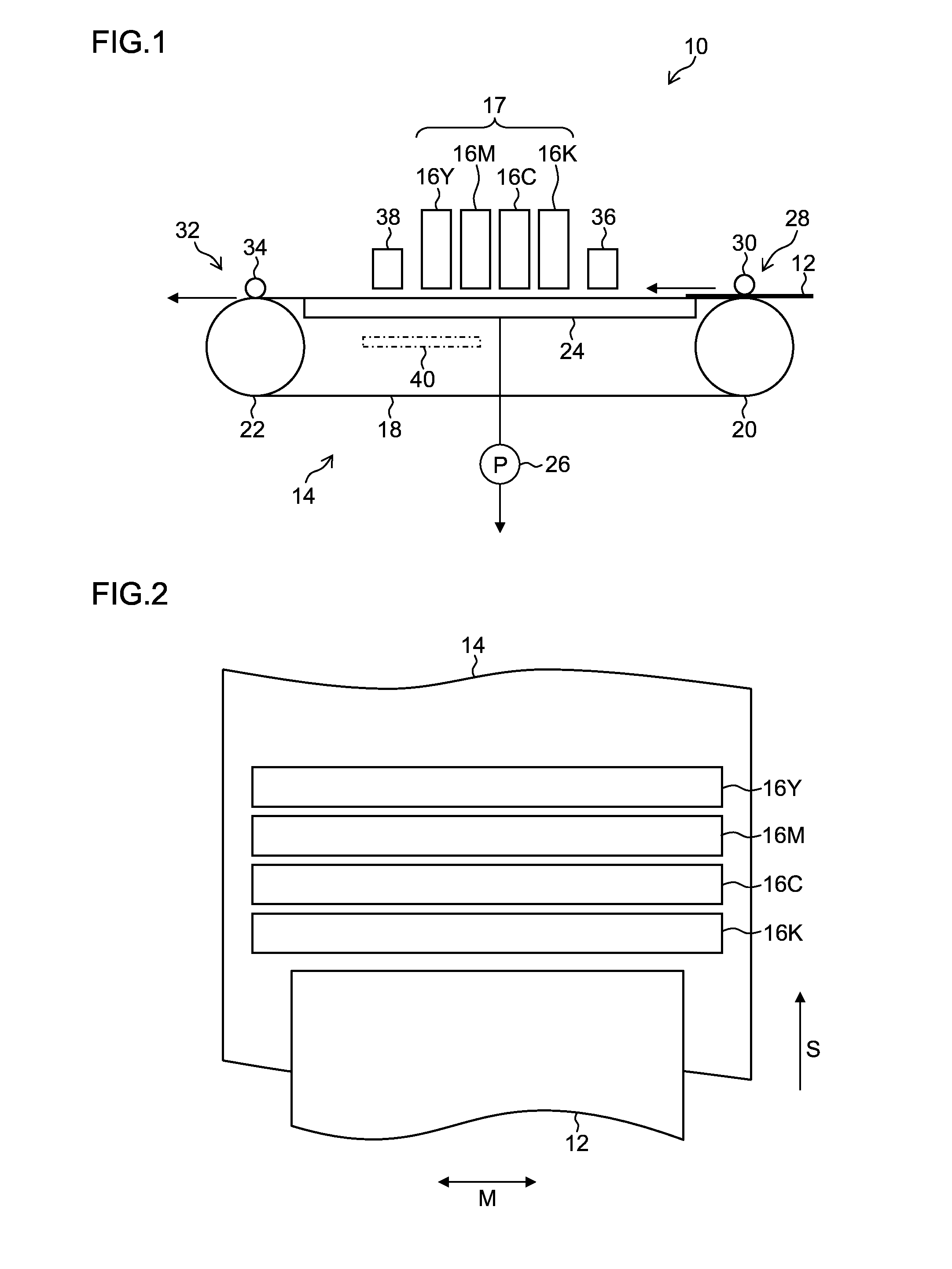
[0068]FIG. 1 is a schematic drawing of an inkjet recording apparatus 10 according to an embodiment of the present invention. The inkjet recording apparatus 10 is an on-demand type of inkjet recording apparatus, and includes a recording medium conveyance unit 14 configured to hold and convey a recording medium 12, and a print unit 17 including inkjet heads 16K, 16C, 16M and 16Y configured to eject and deposit droplets of color inks corresponding to black (K), cyan (C), magenta (M) and yellow (Y) onto the recording medium 12 held on the recording medium conveyance unit 14.

[0069]The recording medium conveyance unit 14 includes: an endless conveyance belt 18, which has a plurality of suction holes (not shown) in a recording medium holding region where the recording medium 12 is held; conveyance rollers including a drive roller 20 and an idle roller 22, about which the conveyance belt 18 is wrapped; a chamber 24, which is arranged on a rear side of the conveyance belt 18 in the recording...


PUM


Abstract

A liquid ejection apparatus includes: a gas chamber surrounding a piezoelectric element in an inkjet head; and a dry gas supply device configured to start supply of dry gas to the gas chamber before supply of electric power to the inkjet head is started, to continue the supply of the dry gas while the supply of the electric power to the inkjet head is continued, and to halt the supply of the dry gas after the supply of the electric power to the inkjet head is halted. While the dry gas supply device halts the supply of the dry gas to the gas chamber, a dry gas supply flow channel opening and closing device is closed to disconnect the dry gas supply device and the gas chamber, and a gas return flow channel opening and closing device is closed to disconnect the gas chamber and the external air.

Description

BACKGROUND OF THE INVENTION[0001]1. Field of the Invention[0002]The present invention relates to a liquid ejection apparatus and a drive method for an inkjet head, and more particularly to driving technology for a piezoelectric device arranged in an inkjet head.[0003]2. Description of the Related Art[0004]As drive methods for inkjet heads in inkjet recording apparatuses, there are known a piezoelectric method and a thermal method. In the piezoelectric method, ink is ejected from a nozzle by using a mechanical distortion of a piezoelectric device. In the thermal method, ink is ejected from a nozzle by using a film boiling effect of ink stored in a liquid chamber connected to the nozzle. The piezoelectric method has a beneficial effect in that the ink ejection volume and ejection velocity can be controlled more readily than the thermal method.[0005]The piezoelectric device used in the inkjet head needs to be constituted of a piezoelectric element made of material having a high piezoel...

Claims


Application Information

Patent Timeline
IPC IPC(8): B41J29/12
CPCB41J29/12B41J2/175B41J2/14233B41J2/195B41J29/377B41J29/38
Inventor SHIBATA, HIROSHIWAKABAYASHI, AKIRAKATAOKA, MASAKIRAI, YOSHIHIRAYUNOKI, KOUSUKE
Owner FUJIFILM CORP
Learn More