Heat dissipation module

a heat dissipation module and heat dissipation module technology, which is applied in the direction of cooling/ventilation/heating modification, semiconductor/solid-state device details, semiconductor devices, etc., can solve the problem that the heat dissipation efficiency of the conventional heat dissipation module cannot meet the increasing heat removal requirements of modern heat-generating electronic components, and the thickness of the conventional heat dissipation module is increased, so as to reduce the thickness of the conventional

Active Publication Date: 2013-05-16
ACER INC
View PDF12 Cites 11 Cited by
  • Summary
  • Abstract
  • Description
  • Claims
  • Application Information

AI Technical Summary

Benefits of technology

[0008]Accordingly, one of the objectives of the present invention is to provide a heat dissipation module, wherein the heat generated by electronic components is directly received by a heat pipe so that the heat dissipation efficiency is increased. The other objective of the present invention is to decrease the thickness of the heat dissipation module so as to meet the demand of making a device using the same thinner. Still the other objective of the present invention is to reduce a number of necessary elements of the heat dissipation module, thus decreasing the weight and reducing the manufacturing cost of the heat dissipation module can be achieved by simplifying the manufacturing process.

Problems solved by technology

However, due to structural limitations, the heat generated by the electronic components cannot be received by the heat pipe directly, which results in the heat dissipation efficiency of the conventional heat dissipation module not meeting the increasing heat removal requirements of modern heat-generating electronic components.
Furthermore, with the arrangement of the heat-receiving portion, the thickness of the conventional heat dissipation module is increased, which hinders the development of thin and light-weight electronic device.

Method used


Image

  • Heat dissipation module
  • Heat dissipation module
  • Heat dissipation module

Examples


Embodiment Construction

[0017]The following description is of the best-contemplated mode of carrying out the invention. This description is made for the purpose of illustrating the general principles of the invention and should not be taken in a limiting sense. The scope of the invention is best determined by reference to the appended claims

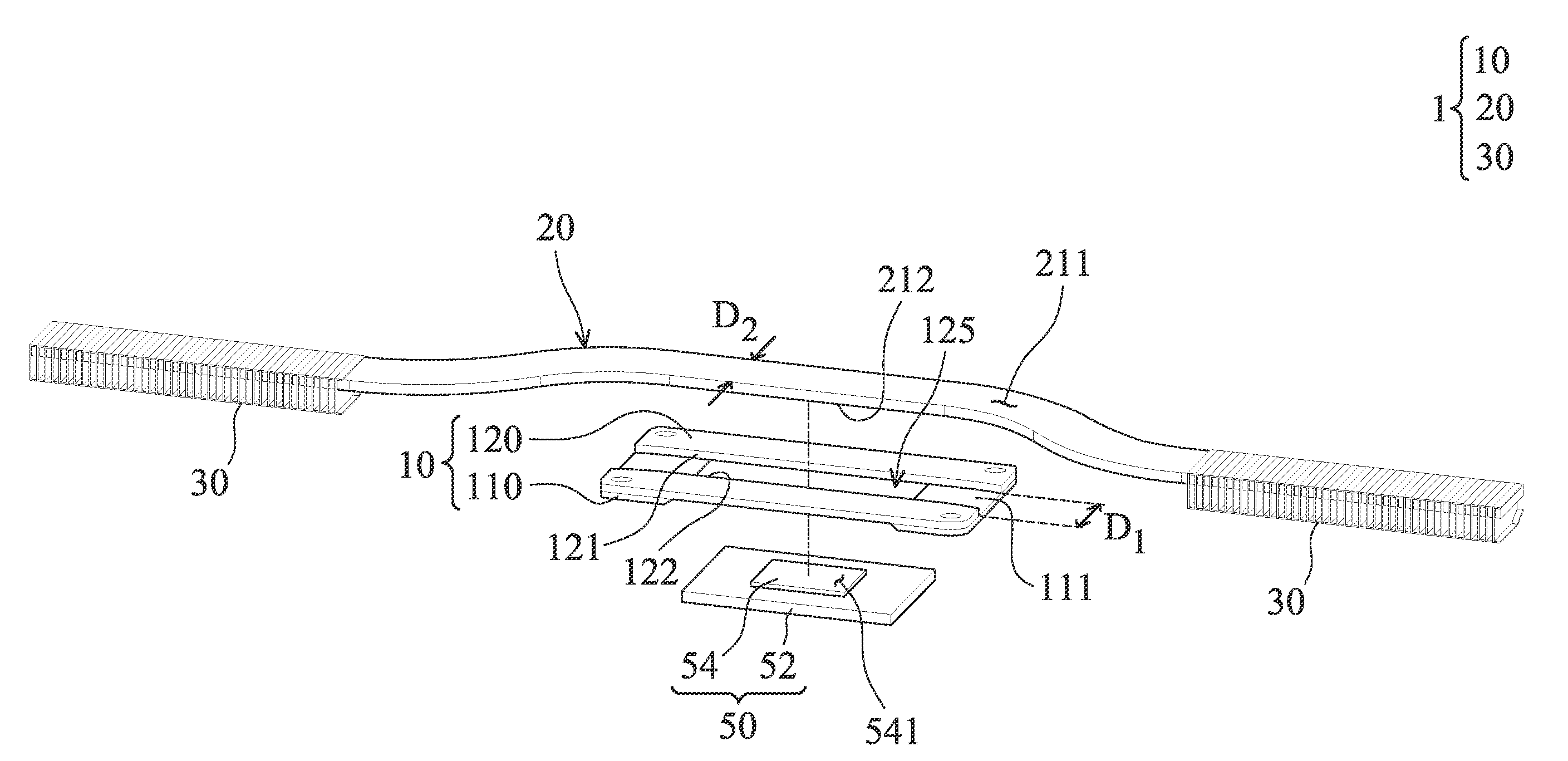
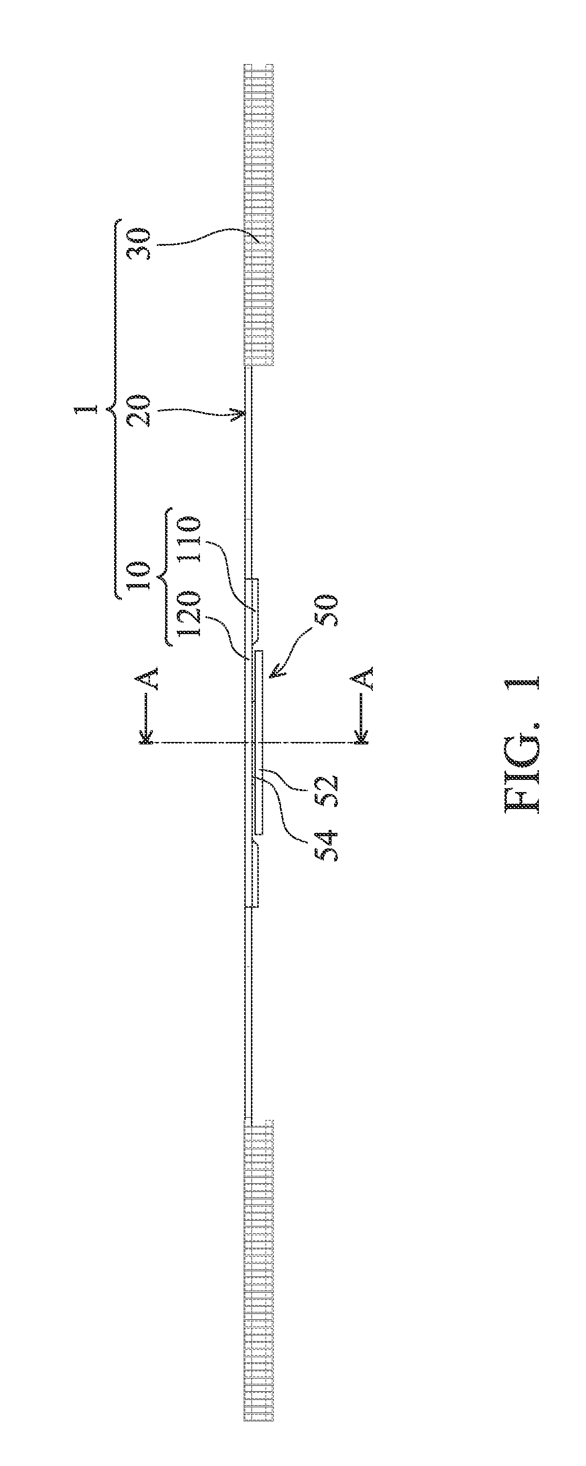
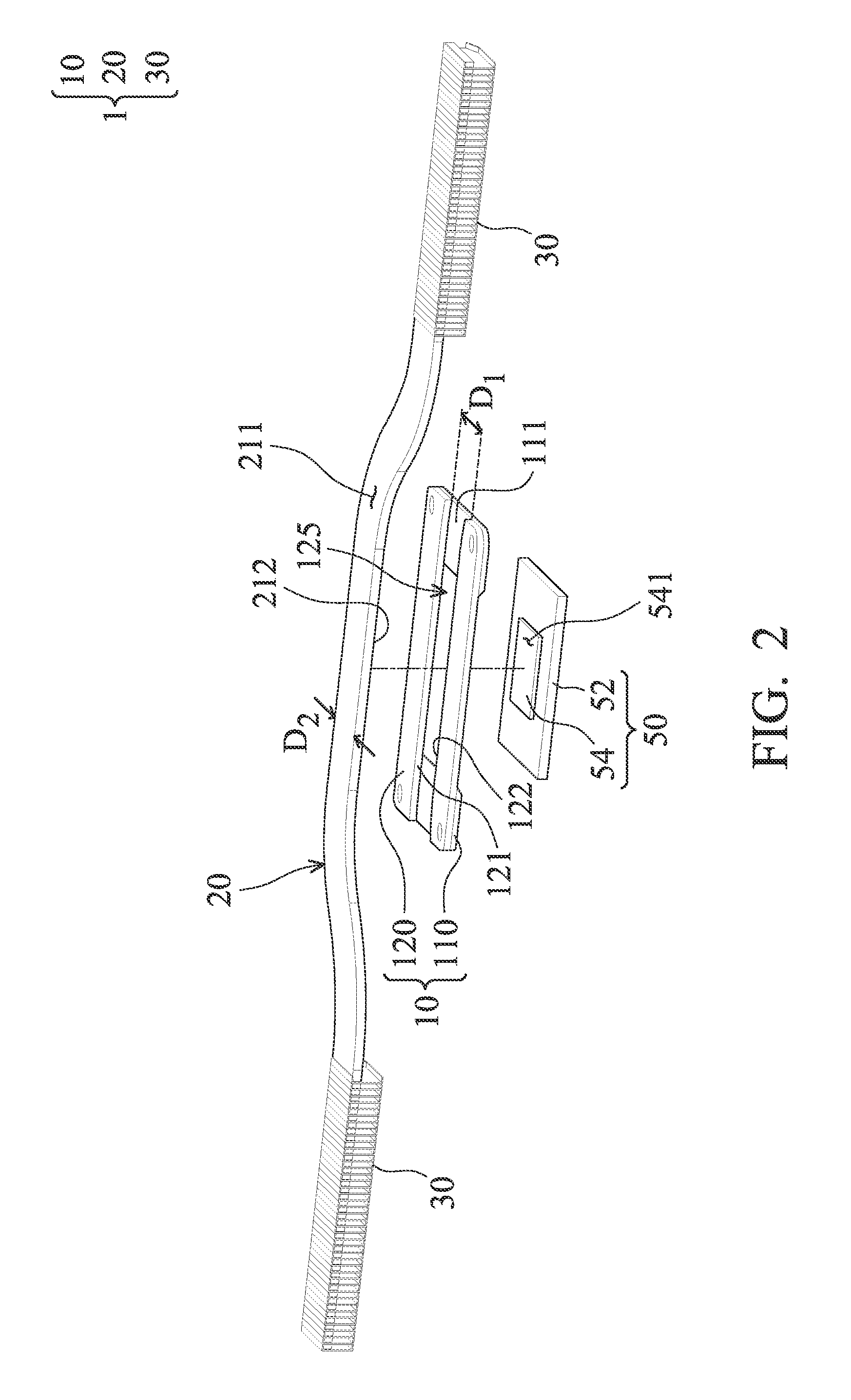
[0018]Please refer to FIGS. 1-3. The heat dissipation module 1 is used for an electronic component 50, to receive and dissipate heat generated from the electronic component 50. In on exemplary embodiment, the electronic component 50 includes a base 52 and a central processing unit 54, hereinafter a CPU, wherein the base 52 is used for connection to a, for example, motherboard of a computer (not shown in FIGs.), and the CPU 54 is disposed on a substantial center of the base 52.

[0019]The heat dissipation module 1 of the embodiment includes a supporting structure 10, a heat pipe 20, and a plurality of heat sinks 30. The supporting structure 10 includes two connecting porti...


PUM


Abstract

A heat dissipation module for an electronic component is provided. The heat dissipation module includes a supporting structure and a heat pipe. The supporting structure is adjacent to the heat electronic component. The heat pipe is connected to the supporting structure by soldering, and the bottom surface of the heat pipe is directly in contact with the upper surface of the electronic component.

Description

CROSS REFERENCE TO RELATED APPLICATIONS[0001]This Application claims priority of Taiwan Patent Application No. 100141751, filed on Nov. 16, 2011, the entirety of which is incorporated by reference hereinBACKGROUND OF THE INVENTION[0002]1. Field of the Invention[0003]The invention relates to a heat dissipation module, and more particularly, to a heat dissipation module which directly contacts to an electronic element.[0004]2. Description of the Related Art[0005]In order to enable portable electronic devices to rapidly process a variety electronic signals, a central processing unit (CPU) and a graphic processing unit (GPU) are often installed therein. When the CPU or GPU operates at a high speed in the electronic device, its temperature is greatly increased. Thus, it is desirable to dissipate heat by using a heat dissipation module to allow the CPU or GPU and other electronic components to function within their normal operating temperature ranges, thereby assuring the quality of data ...

Claims


Application Information

Patent Timeline
Patent Type & Authority Applications(United States)
IPC IPC(8): H05K7/20
CPCH01L23/427F28D15/0233F28D15/0275H01L2924/0002H01L2924/00
Inventor LIAO, WEN-NENG
Owner ACER INC
Why Eureka
Try Eureka