Turbine airfoil and method for thermal barrier coating

a technology of turbine air and thermal barrier coating, which is applied in the direction of liquid fuel engines, vessel construction, marine propulsion, etc., can solve the problems of high loss, only achieve the beneficial effect of efficiency, and lose the trailing edg

Active Publication Date: 2013-05-16
SIEMENS ENERGY GLOBAL GMBH & CO KG
View PDF6 Cites 10 Cited by
  • Summary
  • Abstract
  • Description
  • Claims
  • Application Information

AI Technical Summary

Benefits of technology

[0024]Generally, the inventive turbine airfoil can be manufactured by use of the inventi

Problems solved by technology

However, although such superalloys have considerably high corrosion and oxidation resistance, the high temperatures of the combustion gases in gas turbines require measures to improve corrosion and/or oxidation resistance further.
Trailing edge losses are a significant fraction of the over all losses of a turbo machinery blading.
In particular, thick trailing edges result in higher losses.
However, the beneficial effect on the efficiency can only be achieved if the thickness of the trailing edge is rather small.
In addition, as the flow velocity of the gas is the greatest at the trailing edge of the

Method used


Image

  • Turbine airfoil and method for thermal barrier coating
  • Turbine airfoil and method for thermal barrier coating
  • Turbine airfoil and method for thermal barrier coating

Examples


Embodiment Construction

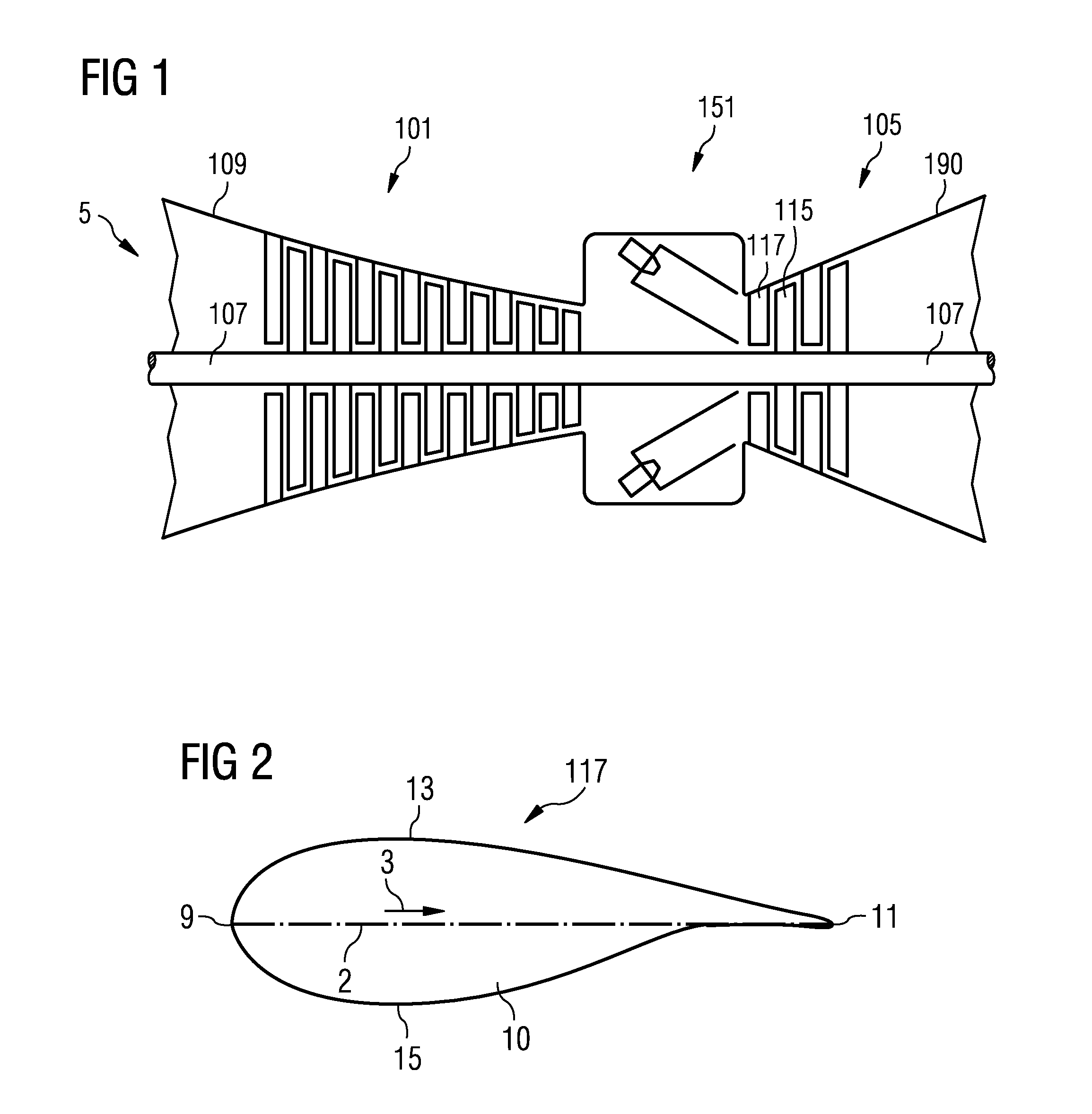
[0029]FIG. 1 schematically shows a gas turbine 5. A gas turbine 5 comprises a rotation axis with a rotor. The rotor comprises a shaft 107. Along the rotor a suction portion with a casing 109, a compressor 101, a combustion portion 151, a turbine 105 and an exhaust portion with a casing 190 are located.

[0030]The combustion portion 151 communicates with a hot gas flow channel which may have a circular cross section, for example. The turbine 105 comprises a number of turbine stages. Each turbine stage comprises rings of turbine blades. In flow direction of the hot gas in the hot gas flow channel a ring of turbine guide vanes 117 is followed by a ring of turbine rotor blades 115. The turbine guide vanes 117 are connected to an inner casing of a stator. The turbine rotor blades 115 are connected to the rotor. The rotor is connected to a generator, for example.

[0031]During operation of the gas turbine air is sucked and compressed by means of the compressor 101. The compressed air is led t...


PUM


Abstract

A turbine airfoil including an airfoil body is disclosed. The airfoil includes a leading edge, a trailing edge, an exterior surface including a suction side extending from the leading edge to the trailing edge and a pressure side extending from the leading edge to a trailing end. The pressure side is located opposite to the suction side on the airfoil body. The complete pressure side of the exterior surface is coated by a thermal barrier coating with a thickness decreasing towards the trailing end.

Description

CROSS REFERENCE TO RELATED APPLICATIONS[0001]This application is the US National Stage of International Application No. PCT / EP2011 / 061640, filed Jul. 8, 2011 and claims the benefit thereof. The International Application claims the benefits of European Patent Office application No. 10171964.9 EP filed Aug. 5, 2010. All of the applications are incorporated by reference herein in their entirety.FIELD OF INVENTION[0002]The present invention relates to a turbine airfoil which can be used in a gas turbine vane or blade. It further relates to a method for thermal barrier coating of a turbine airfoil.BACKGROUND OF INVENTION[0003]The airfoils of gas turbines are typically made of nickel or cobalt based superalloys which show high resistance against the hot and corrosive combustion gases present in gas turbine. However, although such superalloys have considerably high corrosion and oxidation resistance, the high temperatures of the combustion gases in gas turbines require measures to improve ...

Claims


Application Information

Patent Timeline
IPC IPC(8): F01D5/28
CPCF01D5/187F01D5/288F05D2230/90F05D2240/304F05D2250/292F05D2240/122F01D9/06
Inventor BATT, STEPHENCHARLTON, SCOTT
Owner SIEMENS ENERGY GLOBAL GMBH & CO KG
Why Eureka
Try Eureka