High Flux Neutron Source

a neutron source and high flux technology, applied in the field of high-flux neutron sources, can solve the problems of large neutron fluxes, large and expensive, and large safety considerations of samples, and achieve the effect of compact and relatively inexpensive fusion neutron generators

Inactive Publication Date: 2013-05-23
ADELPHI TECH INC
View PDF8 Cites 18 Cited by
  • Summary
  • Abstract
  • Description
  • Claims
  • Application Information

AI Technical Summary

Benefits of technology

[0020]The term “neutron generator” is intended to cover a wide range of devices for the generation of neutrons. The least expensive and compact generator is the “fusion neutron generator” that produces neutrons by fusing isotopes of hydrogen (e.g. tritium and deuterium) by accelerating these isotopes together using modest acceleration energies (e.g. 60 to 200 keV). Various fusion reactions can occur, depending upon the mixture of isotopes used (e.g. DD, DT or TT). These fusion neutron generators are compact and relatively inexpensive compared to linear accelerator devices such as the spallation neutron sources now used in several national laboratories both in the US and abroad. However, these larger, more expensive sources of neutrons can also be used to produce high flux densities of neutrons using the methods described in the present embodiments.

Problems solved by technology

In both techniques samples are bombarded with thermal neutrons, causing the nuclei of the samples to form radioactive isotopes.
Nuclear reactors and accelerators can produce large fluxes of neutrons, but they are large and expensive and have considerable safety considerations that must be addressed in operation.
These issues limit the use of these sources to a few government and regionally sponsored facilities.
Unfortunately, this resulted in low fluxes of neutrons at the sample, which could not activate materials in short enough times for most scientific and commercial purposes.
Previously, the placement of a fast neutron generator in a moderator and the volume of the moderator displaced by the generator limit the flux that can be obtained at the sample.
Previously, one could do this only by increasing the HV power to the generator head, which is limited by cost and size.
This, however, is limited by the conversion efficiency of the fusion process and the high cost of electrical power and high voltage electronics.
This is excessively large power for a clinic or hospital, requiring not only large input powers for the high voltage supply, but also large refrigeration systems for cooling the generator.
Other issues such as high voltage arcing and, consequently, component destruction can occur at such high powers.

Method used


Image

  • High Flux Neutron Source
  • High Flux Neutron Source
  • High Flux Neutron Source

Examples


Embodiment Construction

[0037]In the following descriptions of embodiments of the invention, reference is made to the accompanying drawings that form a part thereof, and in which are shown by way of illustration specific embodiments in which the invention may be practiced. It is to be understood that other embodiments may be utilized and structural changes may be made without departing from the scope of the present invention.

Multiple Fast Neutron Generators Surround a Sample

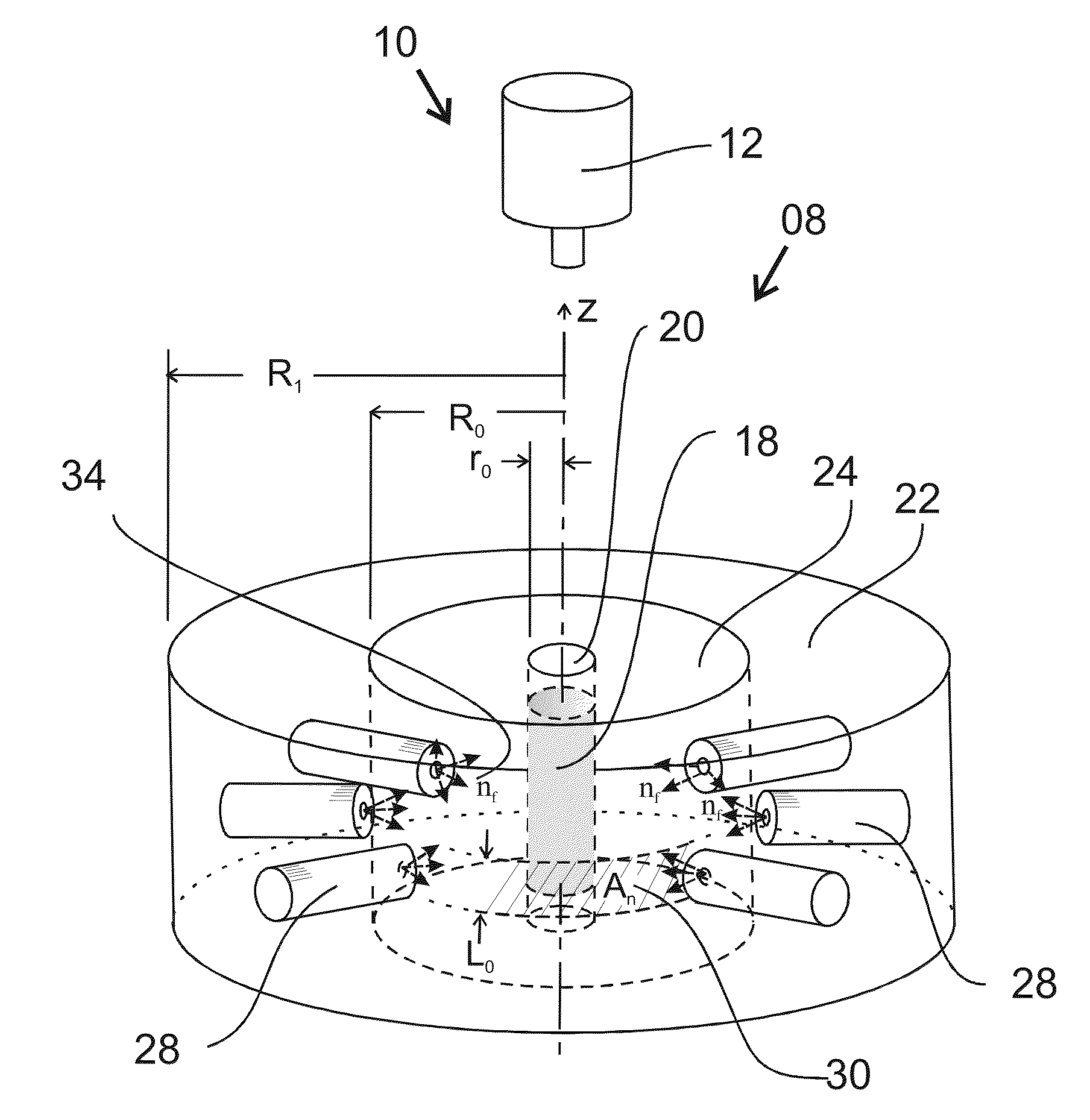
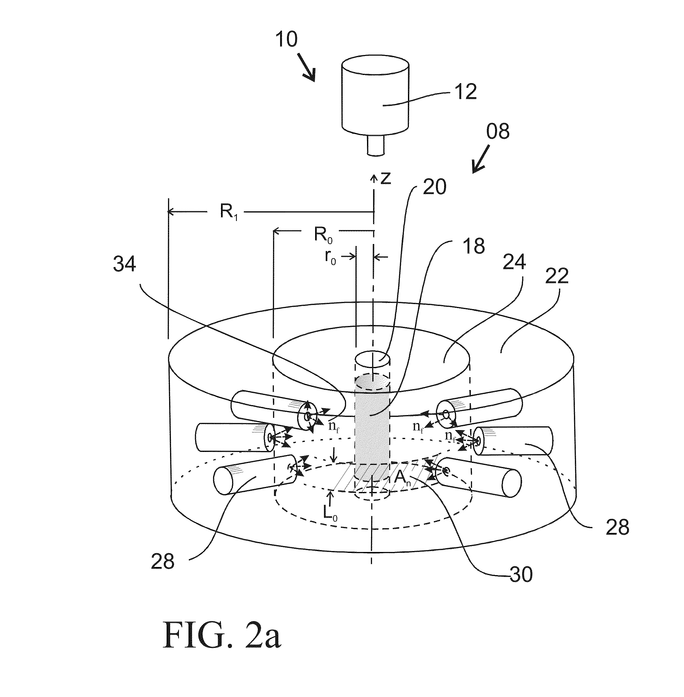
[0038]FIG. 2a is a stylized high-level perspective view of a high flux neutron source 08 according to an embodiment of the present invention, and is used to illustrate salient features that can be viewed as generic to various embodiments discussed below. Adding a gamma-ray detector 12 positioned along the z-axis of the high flux neutron source 08, makes a PGNAA system 10. Main components of the high flux neutron source 08 include fast neutron generators 28, a sample chamber 20, a cylindrical moderator 24, and one or more fast neutron re...


PUM


Abstract

An apparatus for producing thermal or epithermal neutrons in a sample has a plurality of fast neutron sources positioned around a cylindrical or spherical moderator to maximize the neutron flux at a sample placed in a void at the center of the moderator.

Description

CROSS REFERENCED TO RELATED APPLICATIONS[0001]This application is a non-provisional application of provisional patent application Ser. No. 61 / 629,532, filed Nov. 21, 2011 by the present inventors.BACKGROUND OF THE INVENTION[0002]1. Field of the Invention[0003]The present invention is in the technical area of generating high fluxes of neutrons and their use for irradiation, identification and quantification of elements in materials.[0004]2. Description of the Related Art[0005]In the prior art high fluxes of neutrons were obtained from nuclear reactors, accelerators, and fusion reaction neutron generators. These fluxes of neutrons are used for neutron activation analysis (NAA) and prompt gamma neutron activation analysis (PGNAA) for determining the concentrations of elements in many materials. NAA and PGNAA allow discrete sampling of elements as they disregard the chemical form of a sample, and focus solely on nuclei of atoms in the sample. In both techniques samples are bombarded wit...

Claims


Application Information

Patent Timeline
Patent Type & Authority Applications(United States)
IPC IPC(8): G21G1/06G21G1/10
CPCH05H3/06G21G4/02H05H2001/4667H05H1/4652
Inventor PANTELL, RICHARD HARRISGARY, CHARLES KEVINPIESTRUP, MELVIN ARTHUR
Owner ADELPHI TECH INC
Why Eureka
Try Eureka