Process for maximum distillate production from fluid catalytic cracking units (FCCU)

a technology of fluid catalytic cracking unit and distillate, which is applied in the direction of hydrocarbon oil treatment products, physical/chemical process catalysts, metal/metal-oxide/metal-hydroxide catalysts, etc., can solve the problem of reducing the catalyst-to-oil ratio or restricting the riser cracking outlet temperature, reducing the catalytic activity rate, and impairing feed vaporization. , to achieve the effect of reducing the average cr

Inactive Publication Date: 2013-05-23
TECH PRECESS TECH INC
View PDF3 Cites 18 Cited by
  • Summary
  • Abstract
  • Description
  • Claims
  • Application Information

AI Technical Summary

Benefits of technology

[0028]One advantage of the present invention is that it is possible to operate the FCCU with the same catalyst with different catalyst MAT activities that is, partially regenerated catalyst in the feed to a first riser reactor (R1) and fully regenerated catalyst is feed to a second riser reactor (R2), wherein the second riser reactor can be considered a recycle riser. As a result, the bottom products obtained from riser reactor (R1) at the low MAT activity, will be easy to crack in the riser reactor (R2) using a higher MAT catalyst and at higher severity, i.e., operating conditions such as higher riser outlet temperature.
[0029]This FCCU configuration takes advantage of the flexibility offered by any multi-stage regenerator configuration, e.g., two-stage regenerator, where the carbon on regenerated catalyst (CRC) from the first regenerator (RGN1) in partial burn conditions can be manipulated by adjusting the operating conditions, such as, combustion air flowrate. For a given catalyst type characterized by unit cell size, FIG. 4 shows how the MAT activity will change for each 0.1 wt % change in the CRC. Another method for controlling the CRC and the temperature of the cat...

Problems solved by technology

However, decreasing the catalyst-to-oil ratio or restricting the riser cracking outlet temperature in order to maximize LCO/distillate production is accompanied by several disadvantages.
First, a lower catalyst-to-oil ratio decreases the rate of catalytic activity.
Moreover, as the riser outlet temperature is decreased, the temperature in the riser feed zone or mixed zone also decreases, which might impair the feed v...

Method used


Image

  • Process for maximum distillate production from fluid catalytic cracking units (FCCU)
  • Process for maximum distillate production from fluid catalytic cracking units (FCCU)
  • Process for maximum distillate production from fluid catalytic cracking units (FCCU)

Examples


Embodiment Construction

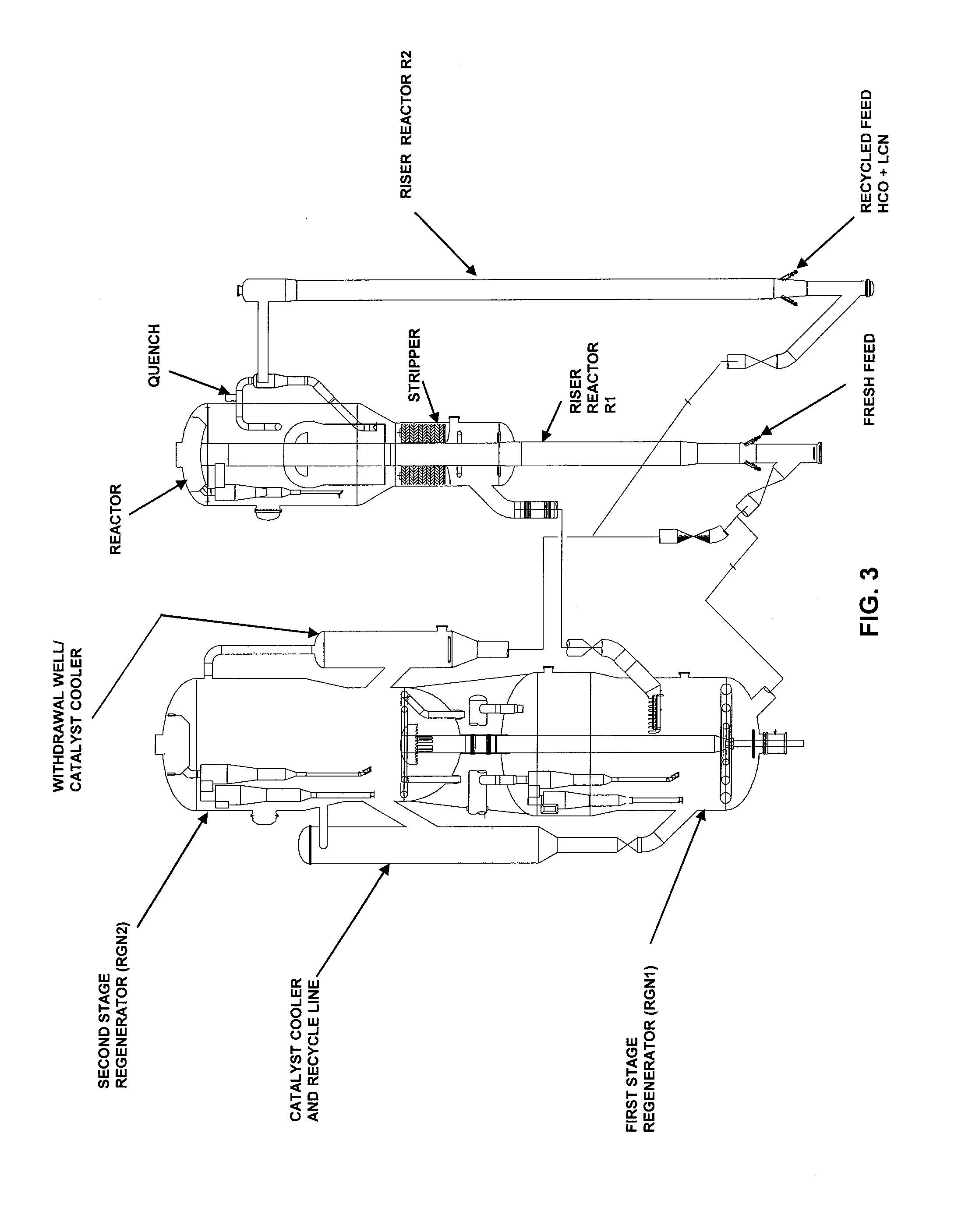
[0041]In accordance with the present invention, an improved hydrocarbon cracking system for maximizing middle distillate production is provided, the system comprising, a single multistage-stage catalyst regeneration unit that provides partially-regenerated catalyst and / or fully-regenerated catalyst to a first riser reactor for receiving a hydrocarbon feed and a second riser reactor for receiving a recycled feed. The partially-regenerated catalyst and the fully-regenerated catalyst have a different MAT activity, due to different CRC levels.

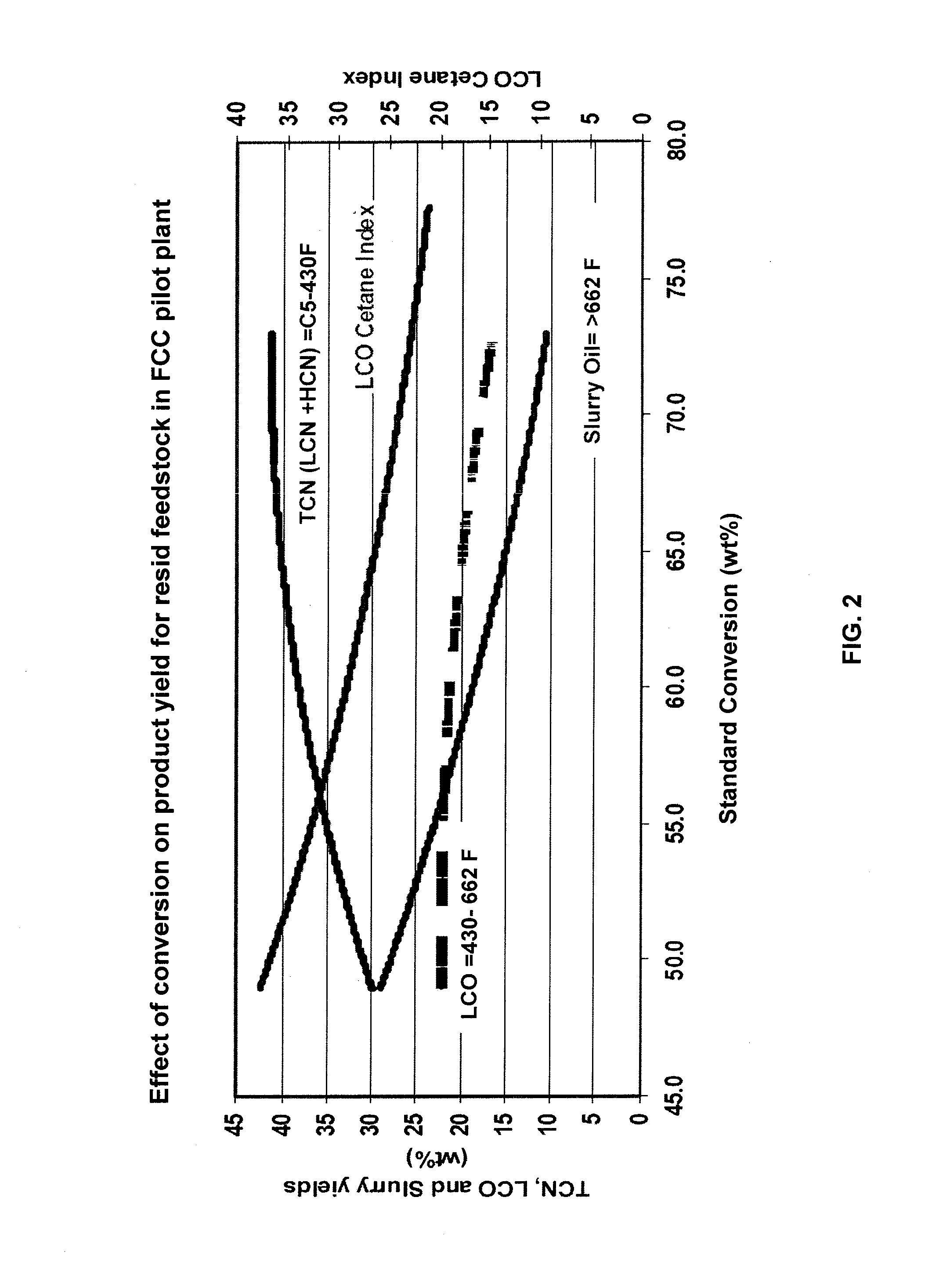
[0042]The invention contemplates a catalytic cracking process designed to maximize middle distillate production from hydrocarbon feedstocks. In the following text, middle distillate will be referred as light cycle oil (LCO), which is a hydrocarbon cut having a boiling range from about 302° F. to about 716° F. As best understood by one skilled in the art, this boiling range may vary to some extent from one refinery to another depending on, for examp...


PUM

PropertyMeasurementUnit
Temperatureaaaaaaaaaa

Abstract

The present invention provides an improved fluidized catalytic cracking process coupled with a two stage regeneration process in which the activity of the circulating catalyst is independently controlled for cracking hydrocarbon feedstocks or the vapors at low severity to produce maximum light cycle oil/distillate in one riser whilst cracking recycle streams comprising heavy cycle oil (HCO), light cracked naphtha (LCN) etc. in a second riser operating at high severity to produce LPG.

Description

BACKGROUND OF THE INVENTION[0001]I. Field of the Invention[0002]The present invention relates to a reactor for increasing or maximizing middle distillate production from hydrocarbon feedstocks. More specifically, the present invention is directed to a unique process and reactor system that increases or maximizes middle distillate, e.g. light cycle oil, production from hydrocarbon feedstocks.[0003]II. Background of the Related Art[0004]It is common commercial practice to produce gasoline, heating oil and diesel fuel by cracking heavier petroleum fractions. One of the major commercial techniques for accomplishing this conversion is fluid catalytic cracking (FCC). In FCC, a feed petroleum fraction such as vacuum gas oil, heavy atmospheric gas oil, etc., is contacted with particles of hot, active catalyst at high temperatures and low pressures of about 1 to 5 atmospheres absolute in the absence of added hydrogen. The catalyst should be in sufficient quantity and at a sufficient temperat...

Claims


Application Information

Patent Timeline
IPC IPC(8): B01J29/40B01J19/00B01J29/04C10G1/00B01J21/08B01J21/12B01J23/02B01J23/00C10G63/08B01J29/08
CPCB01J21/08B01J21/12B01J23/02B01J29/04B01J29/08C10G51/026B01J21/04B01J21/066B01J21/20B01J23/92B01J29/90B01J29/40C10G51/06C10G11/182C10G2400/04C10G2300/701Y02P20/582C07C4/06C10G11/18
Inventor GBORDZOE, EUSEBIUSBORIES, MARCLETZSCH, WARREN STEWARTLEROY, PATRICKSANTNER, CHRISROSS, JR., JOSEPH L.
Owner TECH PRECESS TECH INC
Why Eureka
Try Eureka