Catalyst slurry preparation system and use thereof

a catalyst slurry and preparation system technology, applied in the direction of physical/chemical process catalysts, organic compound/hydride/coordination complex catalysts, transportation and packaging, etc., can solve the problems of unwarranted polymer heterogeneity, low production yield, and production of polymers with undesired properties and/or specifications, etc., to achieve optimal mixing and homogenization of catalyst slurry

Active Publication Date: 2013-05-23
TOTAL RES & TECH FELUY
View PDF37 Cites 1 Cited by
  • Summary
  • Abstract
  • Description
  • Claims
  • Application Information

AI Technical Summary

Benefits of technology

The patent is about using a special impeller system to make a catalyst slurry that can be used in a polymerization reactor to make a polymer with uniform and homogeneous properties. This impeller system consists of two or more double-bladed impellers mounted on a central axis. The use of a magnetic drive system eliminates the risk of leakage and environmental or safety hazards. Overall, this technology allows for efficient and safe mixing of catalyst and diluent to produce high-quality polymers.

Problems solved by technology

Sub-optimal conditions at the start of or during the polymerization reaction may lead to a sub-optimal polymerization conditions resulting for instance in low production yields and / or the production of polymers having undesired properties and / or falling off specifications.
Indeed, (local) catalyst concentration differences in a polymerization reaction result in unwarranted polymer heterogeneity in respect of for instance product density, granulometry and molecular weight (distribution).
As catalyst slurries comprise a solid particulate catalyst suspended in a liquid diluent, such slurries are prone to sedimentation.

Method used


Image

  • Catalyst slurry preparation system and use thereof
  • Catalyst slurry preparation system and use thereof
  • Catalyst slurry preparation system and use thereof

Examples


example 1

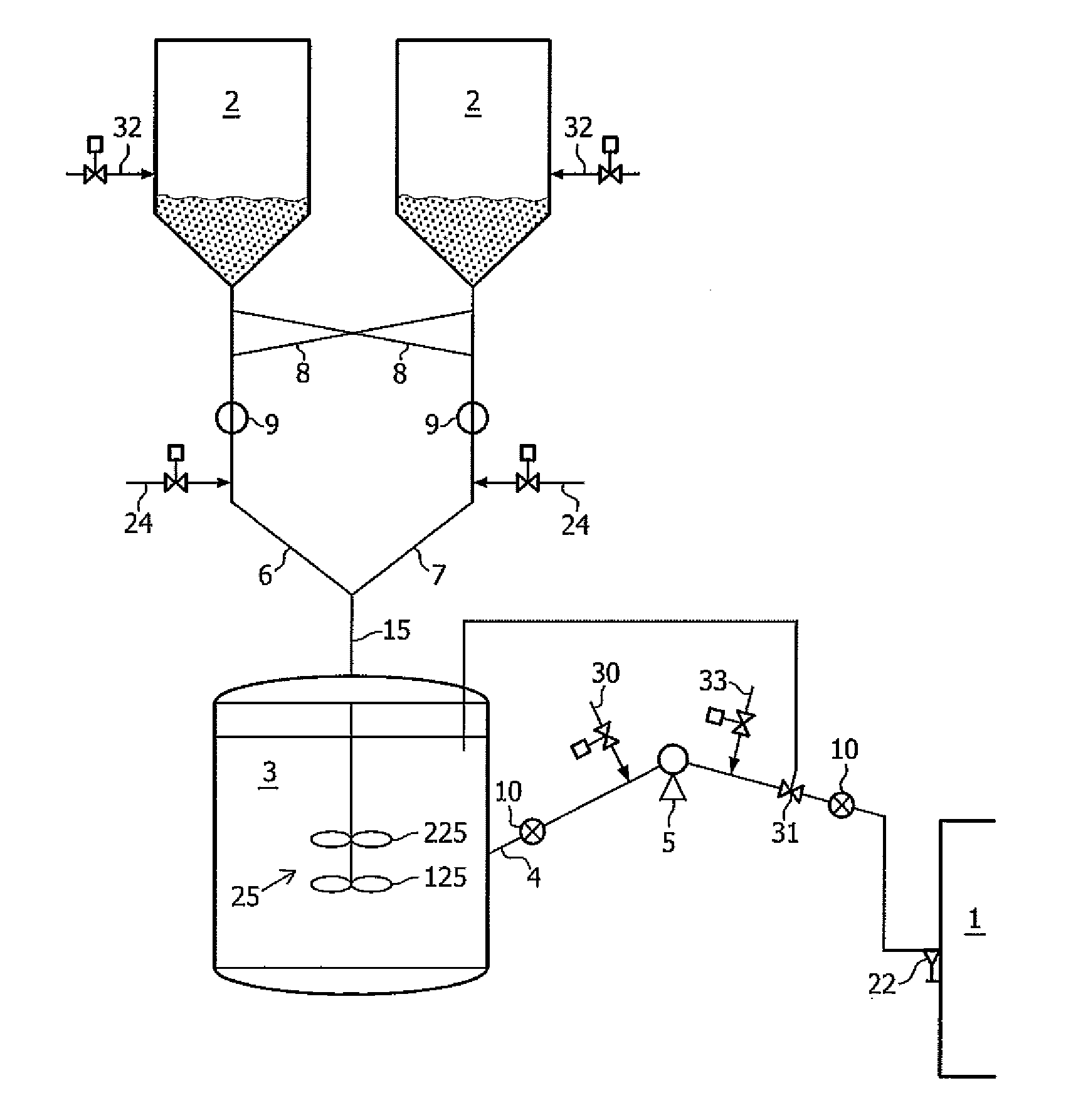
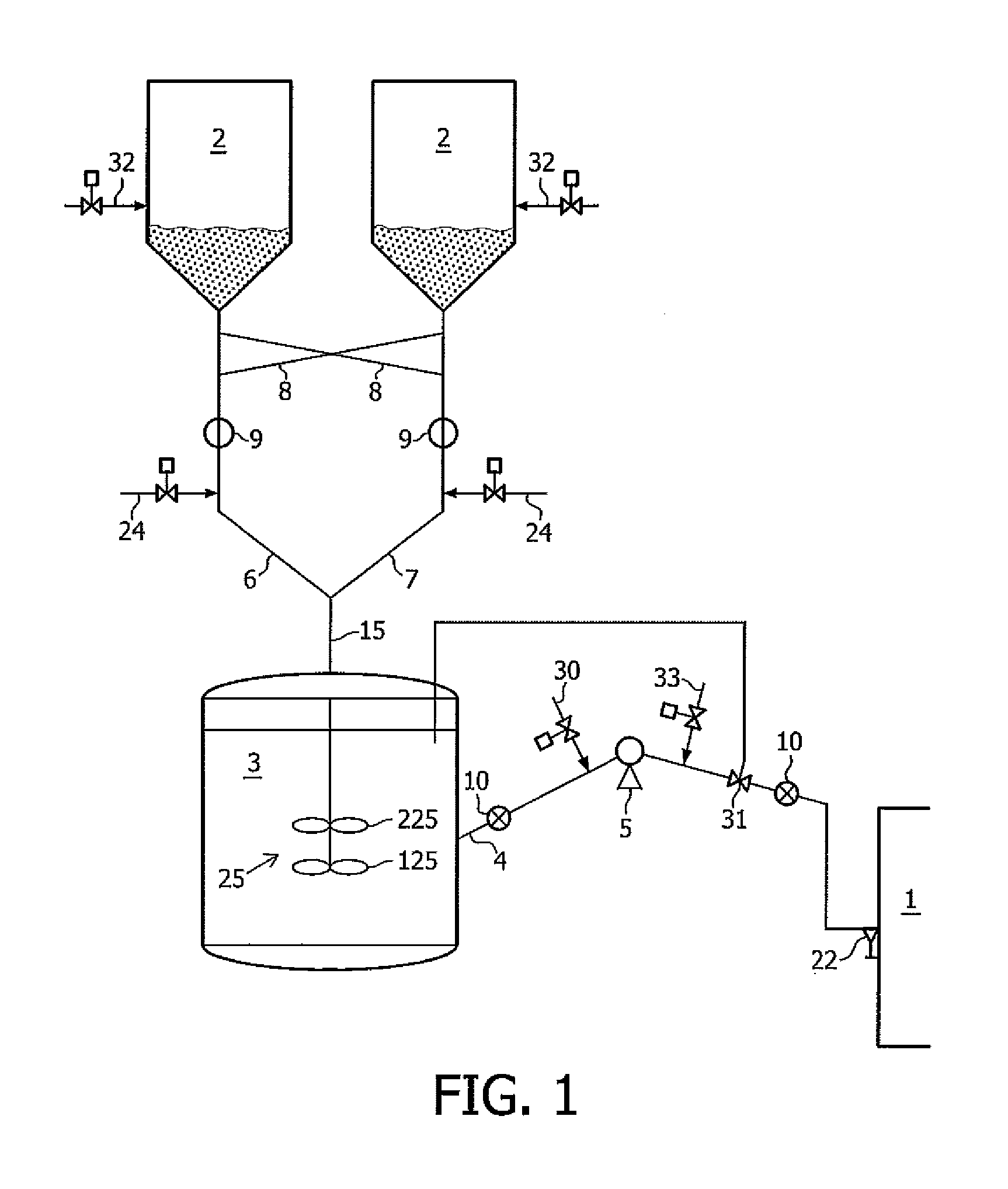
[0109]The present example illustrates the use of a catalyst slurry preparation system according to an embodiment of the invention for preparing diluted catalyst slurry. The polymerization catalyst comprises a metallocene catalyst immobilized on a porous silica support. The metallocene consists in particular of ethylenebis(4,5,6,7-tetrahydro-1-indenyl) zirconium dichloride. The median particle diameter of the polymerization catalyst is 40 μm. The polymerization catalyst can be used to prepare a particulate polyethylene resin in a loop reactor.

[0110]The characteristics of the mixing vessel and the process characteristics for the present example for preparing diluted catalyst slurry are given in Table 1. The flow rate measures how much catalyst slurry is hourly outputted from the mixing vessel, and is thus a measure for catalyst residence time in the mixing vessel as well as catalyst turnover time in the mixing vessel.

TABLE 1volume of mixing vessel (I)500average mixing speed (rpm)325fl...

example 2

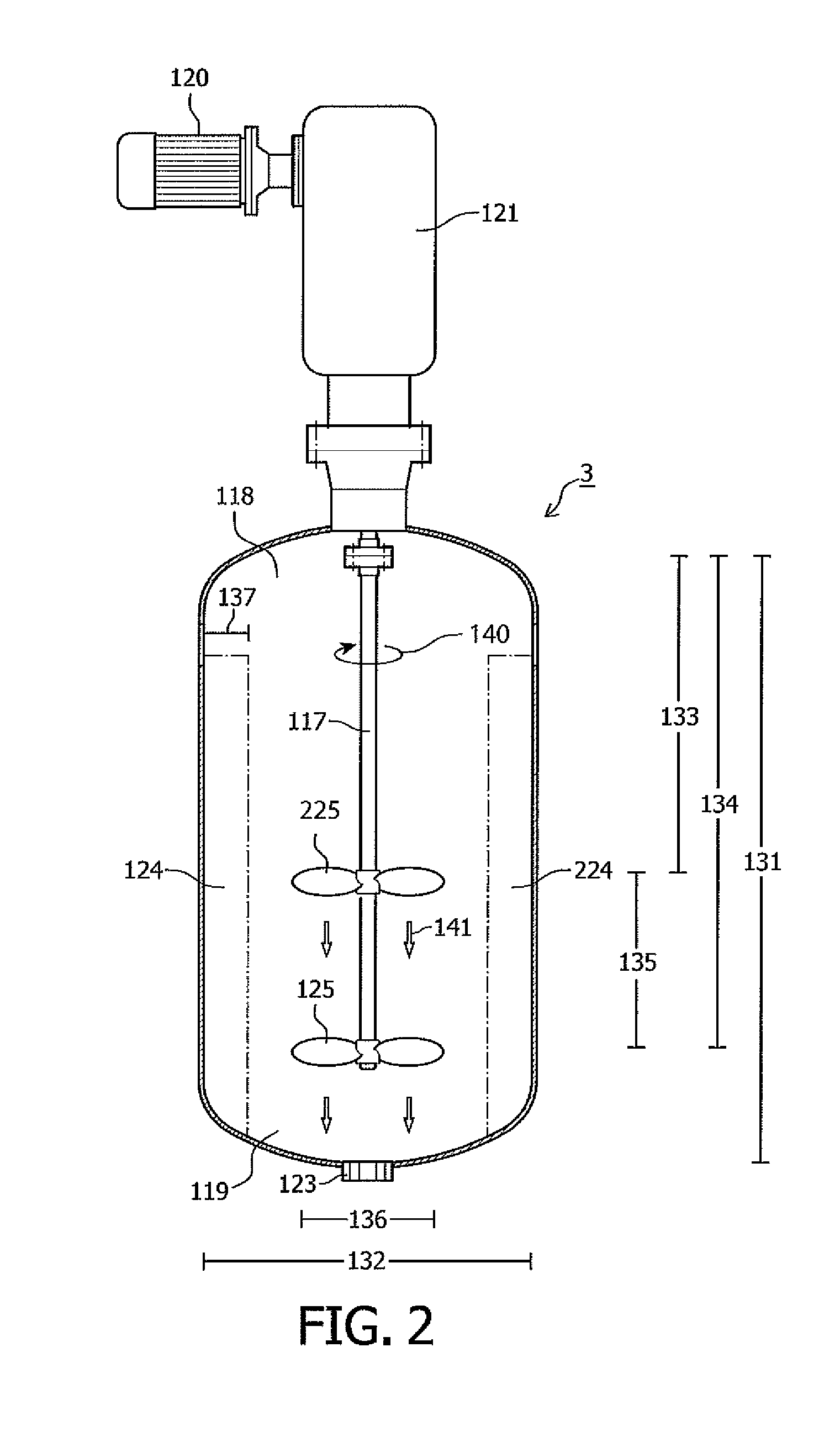
[0112]A mixing tank comprising a magnetic actuated agitator shaft driven by magnetic drive impeller system as schematically illustrated in FIGS. 2 and 6 was used to prepare a catalyst slurry. The catalyst slurry comprised 0.5% by weight of a metallocene catalyst immobilized on a porous silica support in an isobutane diluent. The metallocene consists in particular of ethylenebis(4,5,6,7-tetrahydro-1-indenyl)zirconium dichloride. The mixing tank was operated liquid full. Due to the magnetic coupling, the vessel containing the agitator was hermetically closed and the catalyst slurry could be prepared under liquid full conditions without any leakage.

[0113]Comparatively, a mixing tank comprising an agitator with a mechanical seal could not be used liquid full without observing leakage.


PUM

PropertyMeasurementUnit
pitch angleaaaaaaaaaa
diameteraaaaaaaaaa
diameteraaaaaaaaaa

Abstract

The present invention relates to the use of a catalyst preparation system for the preparation of a diluted catalyst slurry. In particular, the invention relates to a catalyst preparation system comprising a mixing vessel for mixing a particulate catalyst and a liquid hydrocarbon diluent. According to the invention, diluted catalyst slurry is prepared in a mixing vessel comprising a rotatable axial impeller system comprising at least two double-bladed hubs. The invention also relates to a process for preparing diluted catalyst slurry for use in the preparation of a particulate polyethylene product in a loop reactor with the catalyst preparation system as described herein.

Description

TECHNICAL FIELD OF THE INVENTION[0001]The present invention relates to the use of a catalyst preparation system for preparing a diluted catalyst slurry which is to be used for producing a particulate polyethylene product in a loop reactor. In particular, the invention relates to such use, wherein the system comprising a mixing vessel for mixing a particulate catalyst and a liquid hydrocarbon diluent. According to the invention, diluted catalyst slurry is prepared in a mixing vessel comprising a rotatable impeller system comprising double-bladed hubs.BACKGROUND OF THE INVENTION[0002]Polyethylene (PE) is synthesized by polymerizing ethylene (CH2═CH2) monomers. Because it is cheap, safe, stable to most environments and easy to be processed polyethylene polymers are useful in many applications. According to the properties polyethylene can be classified into several types, such as but not limited to LDPE (Low Density Polyethylene), LLDPE (Linear Low Density Polyethylene), and HDPE (High ...

Claims


Application Information

Patent Timeline
Patent Type & Authority Applications(United States)
IPC IPC(8): C08F4/00B01F13/08B01F27/91
CPCB01F7/00633B01F7/1675B01F7/22B01F13/0845B01J8/002B01J8/0035C08F4/00C08F4/65927C08F10/00C08F4/65912B01F13/0827C08F4/65916B29B7/16B01F27/191B01F27/86B01F27/91B01F33/4532C08F2/01C08F10/02B01J8/00B01F27/80B01F33/453B01F33/4531
Inventor BRUSSELLE, ALAINFOUARGE, LOUIS
Owner TOTAL RES & TECH FELUY
Why Eureka
Try Eureka