

Method for producing polyethylene
a polyethylene and polyethylene technology, applied in chemical/physical/physical-chemical stationary reactors, chemical apparatus and processes, chemical/physical/physical-chemical processes, etc., can solve the problems of significant downtime of the reactor, ineffective cost-effective cleaning operations, and time-consuming cleaning operations, so as to avoid equipment cleaning, increase the melt flow index, and reduce the effect of downtim
- Summary
- Abstract
- Description
- Claims
- Application Information
AI Technical Summary
Benefits of technology
Problems solved by technology
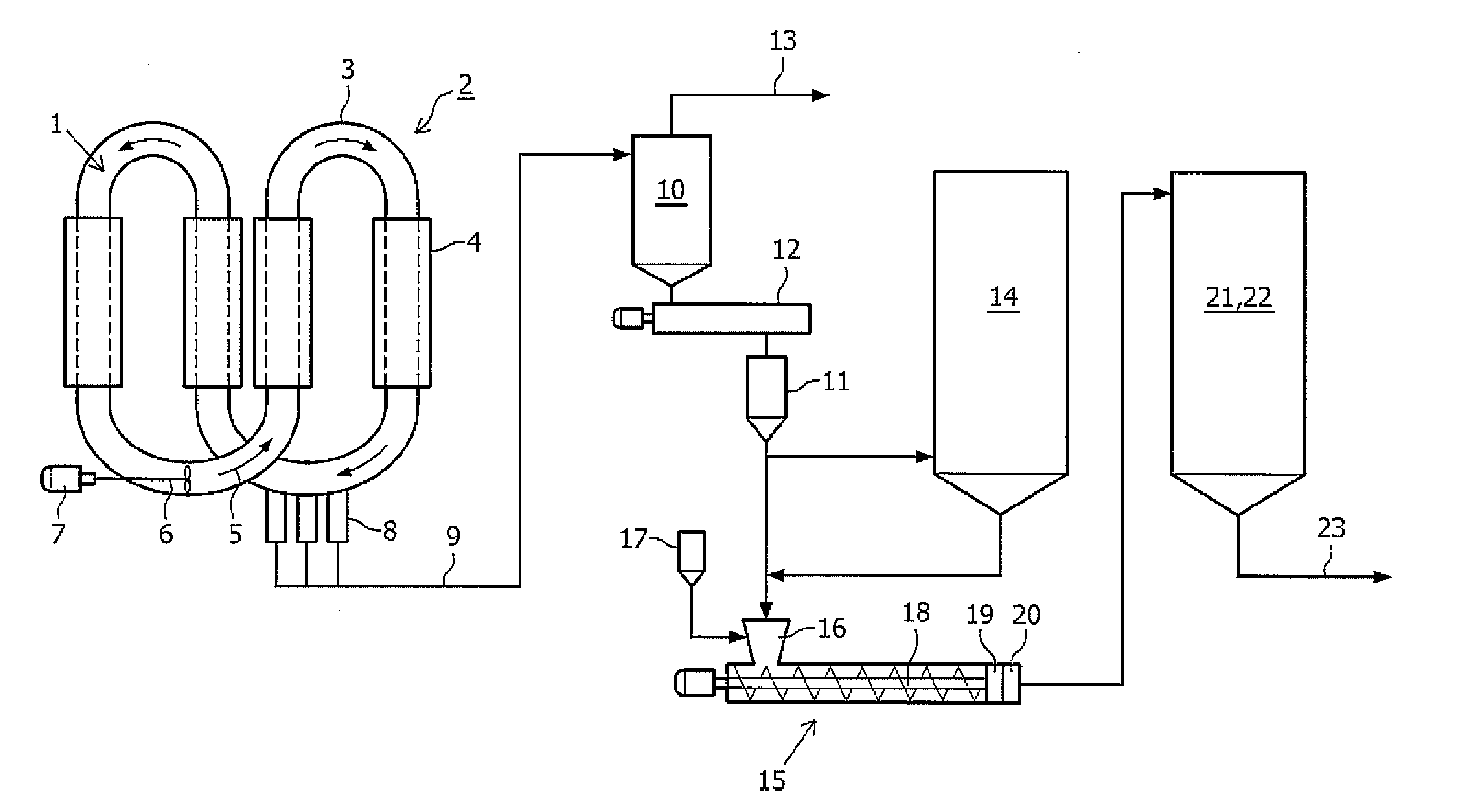
Method used
Image

Examples
example 1
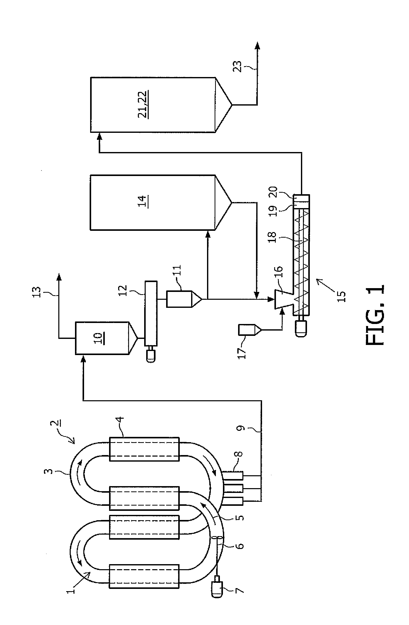
[0082]Two different polyethylene resins were consecutively produced in the same slurry loop reactor: the first polyethylene resin was produced in the presence of a Ziegler-Natta catalyst (ZN). The melt flow index MI2 of the ZN produced polyethylene resin was 0.7 g / 10 min. At the end of the ZN run and after catalyst shift procedure (consisting in killing, emptying and conditioning the reactor), a second polyethylene resin was consecutively produced in the same reactor in the presence of a metallocene catalyst. MI2 of the metallocene produced resin was 8 g / 10 min. The ratio of the MI2 of the ZN produced resin to the MI2 of the metallocene produced resin was 0.09.
[0083]The resins were consecutively extruded. The gel level was measured in the extruded pellets as ppm as a function of time.
[0084]The gels level measured in the extruded resins are shown in FIG. 2A. High level of gels was observed during about 3 days. The specification of the resin was finally corrected thanks to contaminati...
example 2
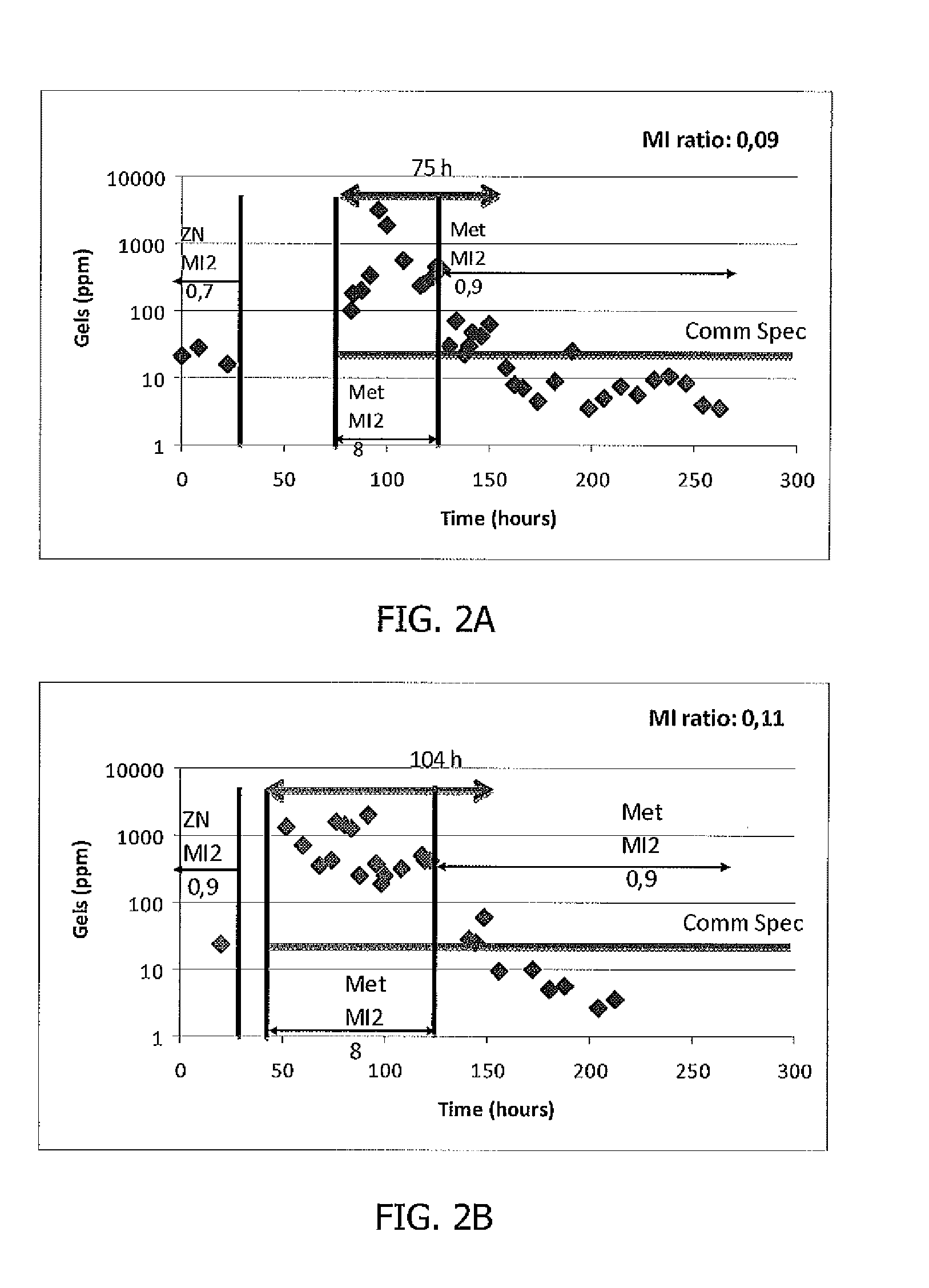
[0085]Two different polyethylene resins were consecutively produced in one slurry loop reactor: a first polyethylene resin with a MI2 of 0.9 g / 10 min was produced in the presence of a Ziegler-Natta catalyst. At the end of the ZN run and after catalyst shift procedure (consisting in killing, emptying and conditioning the reactor), a second polyethylene resin with a MI2 of 8 g / 10 min was consecutively produced in the same reactor in the presence of a metallocene catalyst. The ratio of the MI2 of the first produced polyethylene resin to the MI2 of the second produced polyethylene resin was 0.11.
[0086]The resins were consecutively extruded. The gel level was measured in the extruded pellets as ppm as a function of time.
[0087]The gels level measured in the extruded resins are shown in FIG. 2B. High level of gels was observed during about 4 days. The specification of the resin was finally corrected thanks to contamination dilution with time and production of resins with an MI2 of 0.9.
example 3
[0088]Two different polyethylene resins were consecutively produced in one slurry loop reactor: A first polyethylene resin with a MI2 of 7.5 g / 10 min was produced in the presence of a Ziegler-Natta catalyst. At the end of the ZN run, and in the same reactor, a second polyethylene resin with a MI2 of 0.9 g / 10 min was consecutively produced in the presence of a metallocene catalyst. The ratio of the MI2 of the first produced polyethylene resin to the MI2 of the second produced polyethylene resin was 8.3.
[0089]The resins were consecutively extruded. The gel level was measured in the extruded pellets as ppm as a function of time. The results are shown in FIG. 3A. As shown in the figures no off grades (OG) was observed. The present inventors have shown that gels problem could be controlled. This was achieved by making sure that the melt flow index ratio between the first and the second polyethylene product was at least 0.3.
PUM
| Property | Measurement | Unit |
|---|---|---|
| Melt flow index | aaaaa | aaaaa |
Abstract
Description
Claims
Application Information