FFE Media and FFE Methods Comprising Volatile Separation Media

a separation media and volatile technology, applied in the field of separation media, can solve the problems of ionization techniques used, application does not disclose separation media, and more abundant species have a tendency to “drown” signals

Inactive Publication Date: 2013-05-30
BECTON DICKINSON & CO
View PDF2 Cites 1 Cited by
  • Summary
  • Abstract
  • Description
  • Claims
  • Application Information

AI Technical Summary

Benefits of technology

[0018]It is thus an object of embodiments of the present invention to provide methods that allow the convenient and reproducible separation / fractionation of molecules of interest and allow the separated or at least enriched sample to be subjected to subsequent analysis without having to resort to time- and sample-consuming sample preparation steps prior to the subsequent analysis by, e.g. mass spectroscopy.
[0019]It is a further object of embodiments of the present invention to provide matrix-free media systems for use in FFE separation methods which are advantageous over commonly used FFE media systems since the potentially disturbing buffer compounds (e.g., inorganic salts) can either be easily removed or do not interfere with the subsequent analysis of a separated analyte of interest by, e.g., mass spectrometry.
[0020]The inventors have surprisingly found that separation media comprising volatile buffer compounds are suitable for preparative and analytic FFE separations and allow the successful separation or fractionation of analytes, thereby yielding substantially purified or enriched samples that can be conveniently used in downstream analytic methods such as MS without requiring time-consuming sample preparation steps (e.g., desalting).

Problems solved by technology

In any case, the application does not disclose any separation media.
There are several potential problems that must be resolved in order to successfully carry out a mass spectrometric analysis of a compound of interest, particularly of biomolecules such as proteins.
This presents several significant problems.
First, the two ionization techniques used for large molecules usually only work well when the mixture contains roughly equal amounts of constituents, while in samples of biological origin, different proteins or molecules tend to be present in widely differing amounts.
If such a mixture is ionized using ESI or MALDI, the more abundant species have a tendency to “drown” signals from less abundant ones.
The second problem is that the mass spectrum from a complex mixture is very difficult to interpret due to the overwhelming number of mixture components.
In fact, one of the major barriers to widely applicable MS analysis of biological samples is the successful purification or at least substantial enrichment of the molecules of interest to make them suitable for analysis by MS.
Even the most sophisticated, sensitive instrument cannot generate useful data from impure and / or inadequate amounts of the molecule to be analyzed.
Unfortunately, most biomolecules of interest are found only in very low abundance.
Therefore, sample preparation is one critical, and often technically challenging task in a successful biomolecule MS analysis project today.
Although electrophoresis is a powerful technique for the separation or fractionation of substances, there are some drawbacks using conventional electrophoresis to separate analytes regarding a subsequent MS analysis of the separated analytes.
In fact, many inorganic ions (e.g. metal ions or halogenide ions), which are commonly present in buffer systems for electrophoresis, suppress the mass spectrometric signal, interfere with the ionization process and form adducts to many compounds.
Accordingly, the samples to be analyzed by MS have to be subjected to procedures that are time-consuming and potentially lead to loss of analyte material.

Method used


Image

  • FFE Media and FFE Methods Comprising Volatile Separation Media
  • FFE Media and FFE Methods Comprising Volatile Separation Media
  • FFE Media and FFE Methods Comprising Volatile Separation Media

Examples


example 1

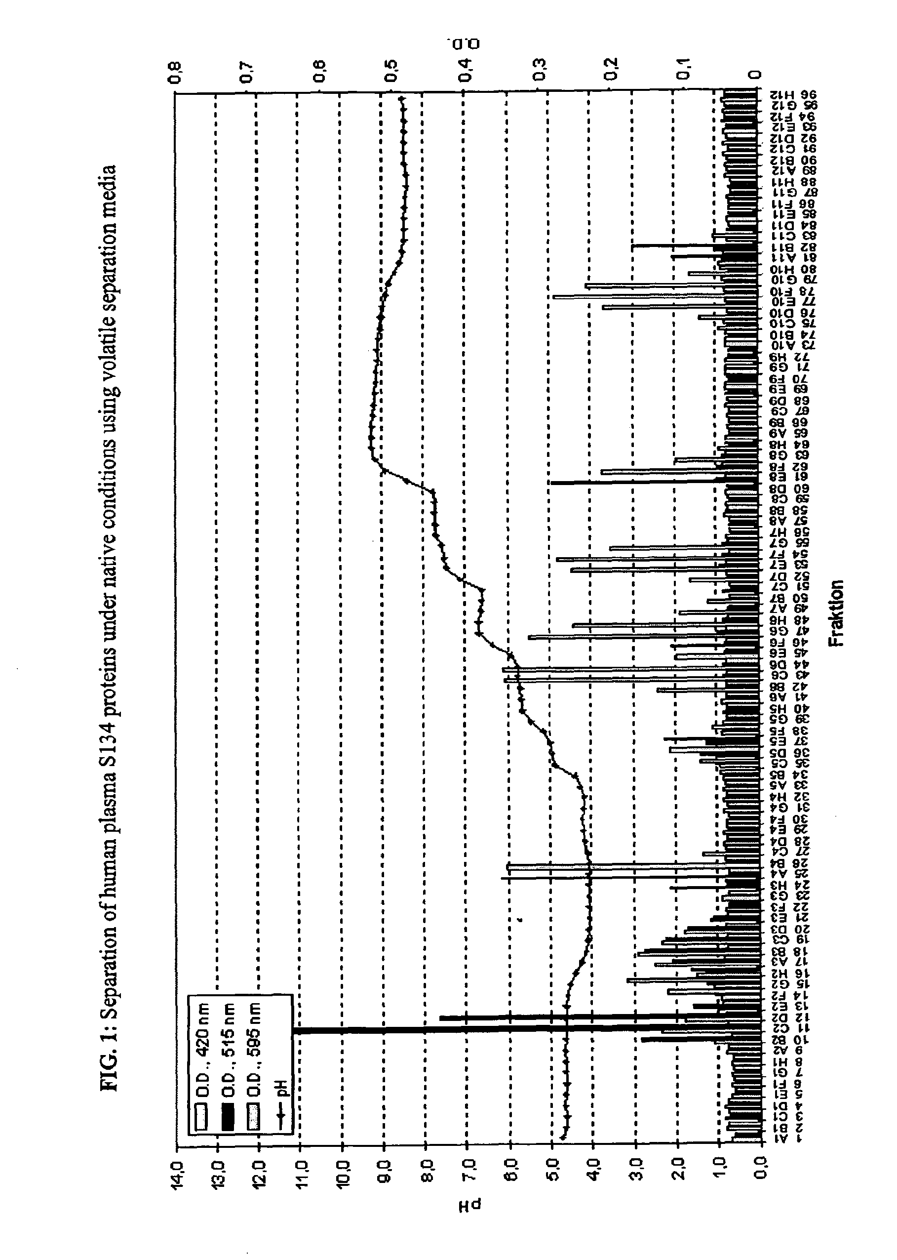
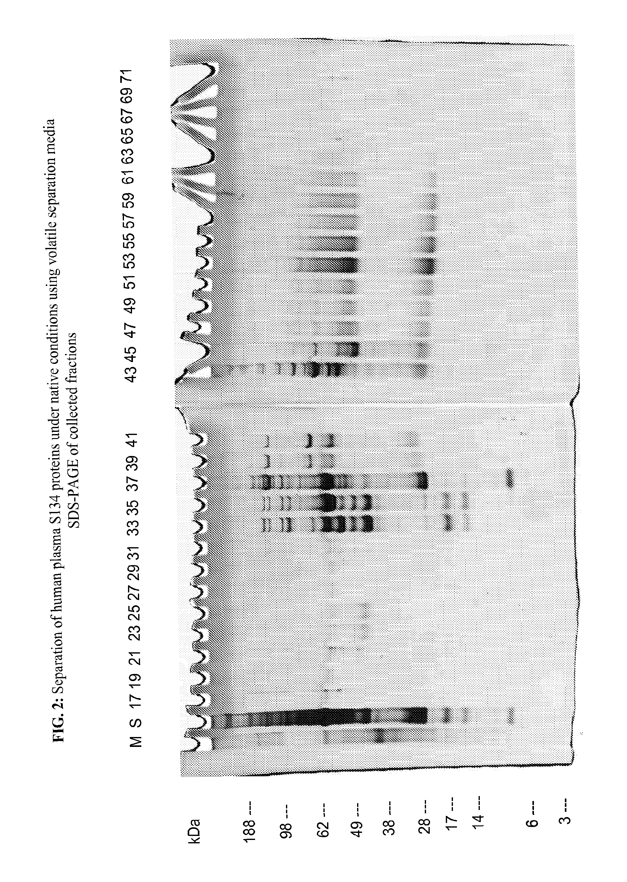
Protein Separation of Human Plasma Under Native Conditions

[0252]The separation medium and stabilizing media were tested on a BD™ Free Flow Electrophoresis System in FF-IEF mode using a quality control solution. The apparatus was set up comprising nine media inlets (E1-E9) and four sample inlets (S1-S4). Anodic stabilizing medium was introduced into inlet E1. The cathodic stabilizing medium was introduced into inlet E9 and the sample was introduced via sample inlet S2. The total time of electrophoresis was approximately 10 minutes. The voltage applied was 500V and the current was 30 mA. The sample and the media were introduced at a flow rate of 1.5 ml / h and 120 ml / h, respectively.

[0253]Anodic Stabilizing Medium:

[0254]450 mM HAc, 225 mM TRIS (pH=4.5; conductivity: 9080 μS / cm) (E1)

[0255]Cathodic Stabilizing Medium:

[0256]225 mM HAc, 1148 mM TRIS (pH=8.40; conductivity: 7730 μS / cm) (E9)

[0257]Separation Medium:

Media Inlet E2E3E4E5E6E7E8Media150 mM15 mM15 mM15 mM15 mM15 mM100 mMHAcTRISTRIS...

example 2

Native Depletion of Human Serum Albumin from Human Plasma

[0260]The separation medium and stabilizing media were tested on a BD™ Free Flow Electrophoresis System in FF-IEF mode using a quality control solution. The apparatus was set up comprising nine media inlets (E1-E9) and four sample inlets (S1-S4). Anodic stabilizing medium was introduced into inlet E1. The cathodic stabilizing medium was introduced into inlet E9 and the sample was introduced via sample inlet S2. The total time of electrophoresis was approximately 10 minutes. The voltage applied was 500V and the current was 31 mA. The sample and the media were introduced at a flow rate of 1.5 ml / h and 120 ml / h, respectively.

[0261]Anodic Stabilizing Medium:

[0262]450 mM HAc, 225 mM TRIS (pH=4.5; conductivity: 9080 μS / cm) (E1;

[0263]Cathodic Stabilizing Medium:

[0264]225 mM HAc, 1148 mM TRIS (pH=8.40; conductivity: 7730 μS / cm) (E9);

[0265]Separation Medium:

Media InletE2E3E4E5E6E7E8Media150 mM15 mM15 mM15 mM15 mM15 mM100 mMHAcTRISTRIST...

example 3

FFE Separation in Cyclic Interval Mode

[0268]The separation medium and stabilizing media were tested on a BD™ Free Flow Electrophoresis System in FF-IEF mode using a quality control solution. The apparatus was set up comprising nine media inlets (E1-E9) and four sample inlets (S1-S4). Anodic stabilizing medium was introduced into inlet E1. The cathodic stabilizing medium was introduced into inlet E9 and the sample was introduced via sample inlet S2. The total time of electrophoresis was approximately 40 minutes. The voltage applied was 500V and the current was 30 mA. The sample and the media were introduced at a flow rate of 1.5 ml / h and 150 ml / h, respectively. The run was performed in cyclic interval FF-IEF mode at 50 ml / h and the fractionated sample was eluted at 150 ml / h.

[0269]Anodic Stabilizing Medium:

[0270]450 mM HAc, 225 mM TRIS (pH=4.54; conductivity: 9120 μS / cm) (E1);

[0271]Cathodic Stabilizing Medium:

[0272]225 mM HAc, 1148 mM TRIS (pH=8.40; conductivity: 8040 μS / cm) (E9);

[027...


PUM

PropertyMeasurementUnit
temperatureaaaaaaaaaa
pKaaaaaaaaaaa

Abstract

The present invention provides methods and separation media for separating analytes of interest via free flow electrophoresis (FFE) using volatile buffer systems. The separation media provided herein allow a convenient separation of the analytes by electrophoresis, and offer the additional advantage that the buffer compounds and the solvent can be easily and residue-free removed after the electrophoretic separation step. Furthermore, methods for mass spectrometric analysis of analytes comprising an FFE method and kits for carrying out FFE separations with volatile buffer systems are also provided. Preferably, the volatile buffer system is TRIS acetate.

Description

FIELD OF THE INVENTION[0001]An embodiment of the present invention relates to separation media comprising a volatile buffer system in free flow electrophoresis (FFE). The separation media provided herein allow a convenient separation of the analytes by electrophoresis, and offer the further advantage that the buffer compounds and the solvent can be easily and residue-free removed by evaporation after the electrophoretic separation step. Furthermore, methods for separating analytes by FFE, methods for mass spectrometric analysis of analytes comprising an FFE separation step, and kits for carrying out FFE separations are provided by embodiments of the present invention.BACKGROUND OF THE INVENTION[0002]Electrophoresis is a well-established technology for separating particles based on the migration of charged particles under the influence of a direct electric current. Several different operation modes such as isoelectric focusing (IEF), zone electrophoresis (ZE) and isotachophoresis (IT...

Claims


Application Information

Patent Timeline
Patent Type & Authority Applications(United States)
IPC IPC(8): G01N27/26
CPCG01N27/44747G01N27/26G01N27/44795G01N27/44769
Inventor WEBER, GERHARDNISSUM, MIKKEL
Owner BECTON DICKINSON & CO
Why Eureka
Try Eureka