Pulsed laser machining method and pulsed laser machining equipment, in particular for welding with variation of the power of each laser pulse

a laser machining and laser pulse technology, applied in the field of laser welding, can solve the problems of secondary problems detrimental to the quality of welds, the quantity of energy finally absorbed becomes too large, etc., and achieves high luminous power, high conversion rate, and high power

Inactive Publication Date: 2013-05-30
ROFIN LASAG AG
View PDF7 Cites 30 Cited by
  • Summary
  • Abstract
  • Description
  • Claims
  • Application Information

AI Technical Summary

Benefits of technology

[0013]By limiting the duration of high power simply to the initial phase, the power in the initial phase, where the frequency doubled light is mostly absorbed, is thus controlled differently from in the intermediate phase during which the actual weld takes place and where the light at the initial wavelength is well absorbed. Further, this enables a relatively high power to be supplied in the initial phase to increase the conversion rate by the non-linear crystal. Indeed, this conversion rate increases proportionally to the incident luminous intensity, and consequently the frequency doubled luminous power increases proportionally to the square of the incident power. Thus, in order to obtain a maximum of frequency doubled light in the initial phase, it is advantageous to provide a relatively high luminous power in this initial phase. Since the power emitted in this initial phase does not define the power emitted in the subsequent phase, this does not cause any problems of machining quality. A relatively high power peak can thus be provided in this initial phase which causes a rapid and efficient start of machining at the surface of the machined material. This has another advantage since it is not necessary, as in the prior art, to incorporate the non-linear crystal in the laser cavity to obtain a certain proportion of frequency doubled light. It is thus possible to take a conventional laser source and arrange a heat-adjusted unit comprising the non-linear crystal on the optical axis of the laser beam exiting the laser source.

Problems solved by technology

The initial weld efficiency increases, but the overall quantity of energy finally absorbed becomes too great and causes secondary problems detrimental to the quality of the weld, particularly to the surface state after welding.

Method used


Image

  • Pulsed laser machining method and pulsed laser machining equipment, in particular for welding with variation of the power of each laser pulse
  • Pulsed laser machining method and pulsed laser machining equipment, in particular for welding with variation of the power of each laser pulse
  • Pulsed laser machining method and pulsed laser machining equipment, in particular for welding with variation of the power of each laser pulse

Examples


Embodiment Construction

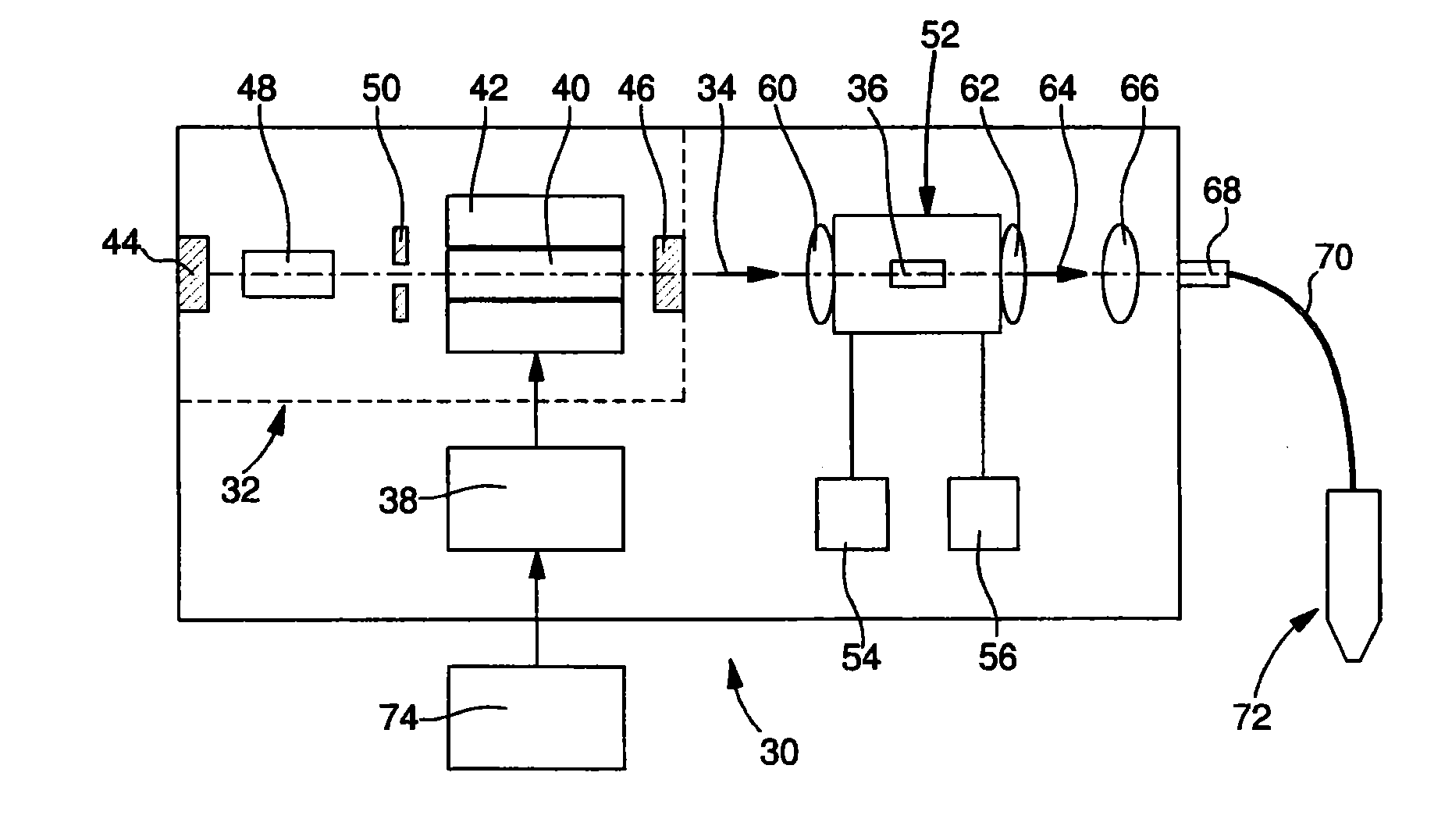
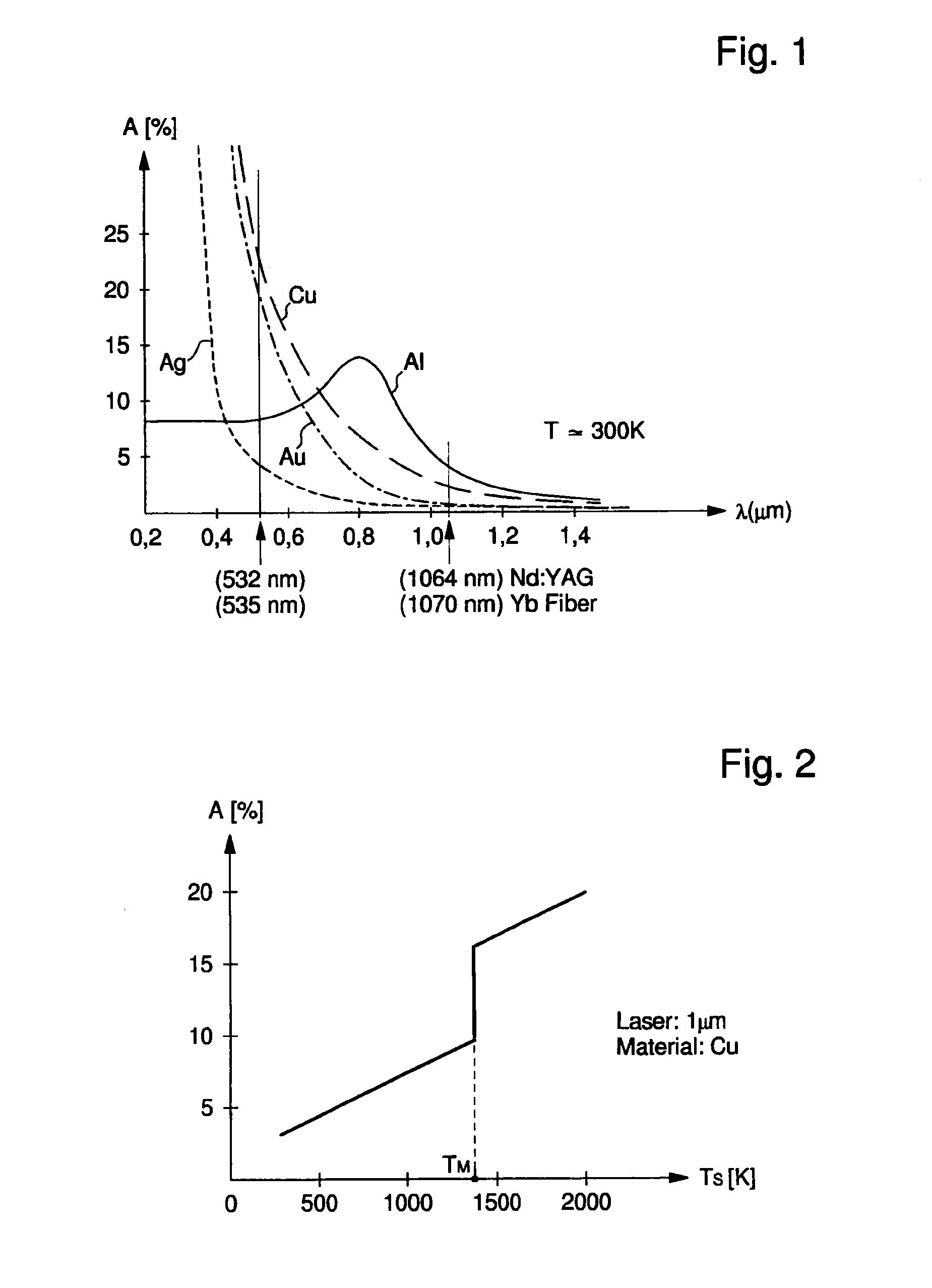
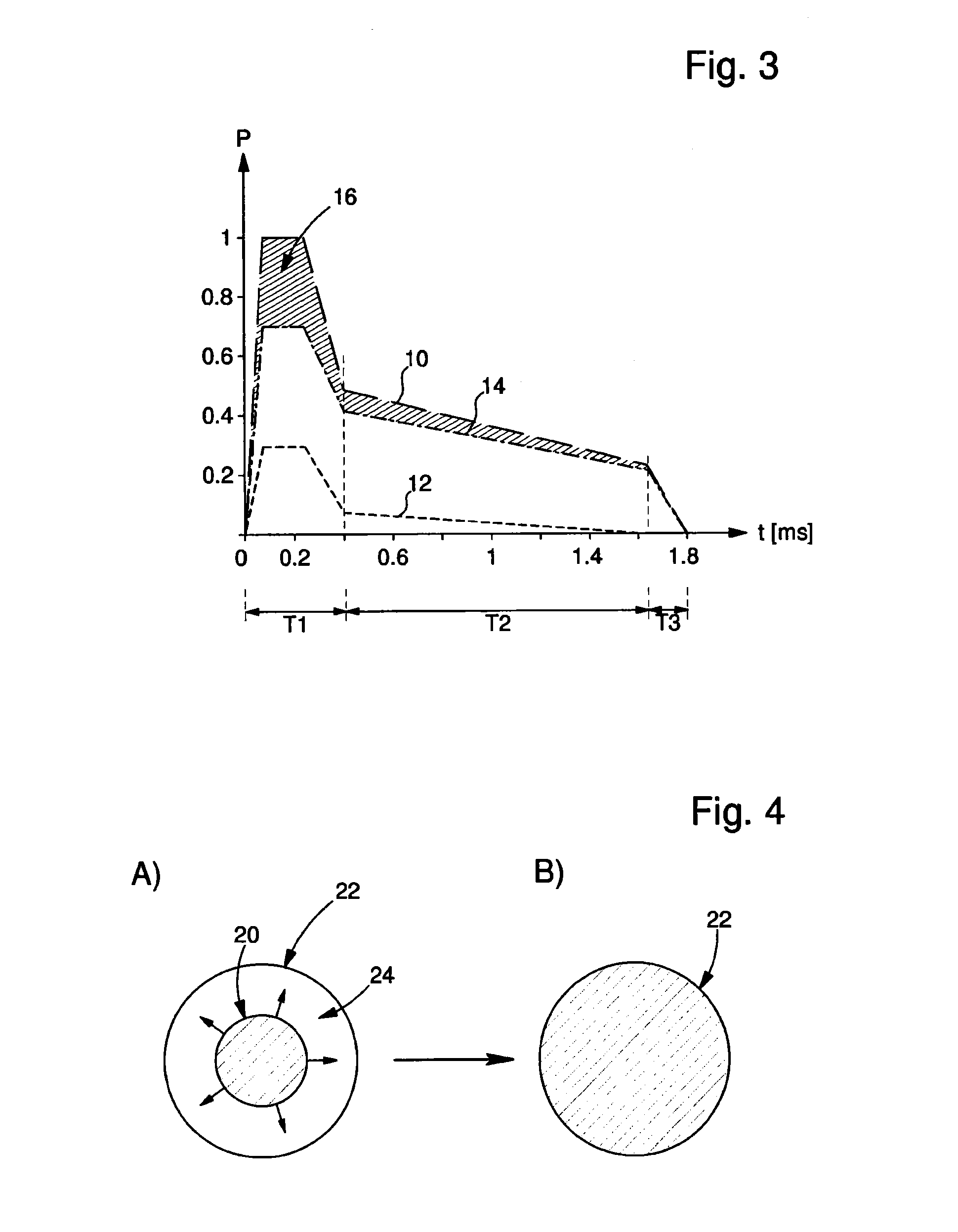
[0021]The laser machining method of the invention includes the following steps:[0022]A) Generating, by means of a laser source, a laser beam having a wavelength of between 700 and 1200 nanometres formed of a series of laser pulses.[0023]B) Doubling the frequency of one part of the laser beam by means of a non-linear crystal.[0024]C) Varying the power during each emitted laser pulse so that, throughout the period of this laser pulse, the power profile has a maximum peak power or part of the pulse with a maximum power in an initial sub-period T1, and in a second intermediate sub-period T2 of longer duration than the initial sub-period and occurring thereafter, a lower power than said maximum power throughout the entire intermediate sub-period.

[0025]The value of the maximum power variation is at least two times higher than the mean power throughout the period of the laser pulse and the time of increase to said maximum power from the start of each laser pulse is less than 3 / 10 milliseco...


PUM

PropertyMeasurementUnit
wavelengthaaaaaaaaaa
poweraaaaaaaaaa

Abstract

A laser machining method includes A) generating, by a laser source, a laser beam having an initial wavelength between 700 and 1200 nanometers of laser pulses; B) doubling frequency of one part of the laser beam by a non-linear crystal; C) varying power throughout each emitted laser pulse so that the power profile has a maximum peak power or part of the pulse with a maximum power in an initial sub-period, and throughout an intermediate sub-period of longer duration than the initial sub-period, a lower power than the maximum power. The maximum power value is at least two times higher than the mean power throughout the laser pulse and an increase time to maximum power from a start of each laser pulse is less than 0.3 milliseconds. The machining method can concern welding highly reflective metals, copper, gold, silver, or an alloy including one of these metals.

Description

FIELD OF THE INVENTION[0001]The present invention concerns the field of laser welding and in particular the laser welding of highly reflective materials, such as copper, gold, silver, aluminium or an alloy comprising one of these metals. More specifically, the invention concerns a laser welding method and an equipment for implementing said method where the coherent light source generates a laser beam with a wavelength of between 700 and 1200 nanometres, for example an Nd:YAG laser or fibre laser. A non-linear crystal is provided for partially doubling the frequency of the laser beam so as to increase machining efficiency.BACKGROUND OF THE INVENTION[0002]A laser welding equipment is known from U.S. Pat. No. 5,083,007 comprising an Nd:YAG laser source optically pumped using a flash lamp and generating a coherent light with a wavelength of 1064 nanometres (nm), and a non-linear crystal (for example LiNbO3 or KTP) arranged in the resonant cavity, said crystal partially doubling the freq...

Claims


Application Information

Patent Timeline
Patent Type & Authority Applications(United States)
IPC IPC(8): B23K26/20
CPCB23K26/063B23K26/20B23K2203/12B23K2203/10B23K2203/08B23K26/0622B23K26/22B23K2103/08B23K2103/10B23K2103/12B23K26/21H01S3/109
Inventor DUERR, ULRICHRUETTIMANN, CHRISTOPHFREI, BRUNO
Owner ROFIN LASAG AG
Why Eureka
Try Eureka