Communication through multiplexed one-dimensional optical signals

a one-dimensional optical signal and communication technology, applied in the field of optical communication equipment, can solve the problems of limiting transmission performance, coding-gain differences among various implementable fec codes usually not exceeding a certain maximum value, and the cost of reducing forward-channel bandwidth is a concomitant increase in the required forward-channel bandwidth. the effect of nonlinear fiber penalty

Active Publication Date: 2013-05-30
WSOU INVESTMENTS LLC
View PDF4 Cites 68 Cited by
  • Summary
  • Abstract
  • Description
  • Claims
  • Application Information

AI Technical Summary

Benefits of technology

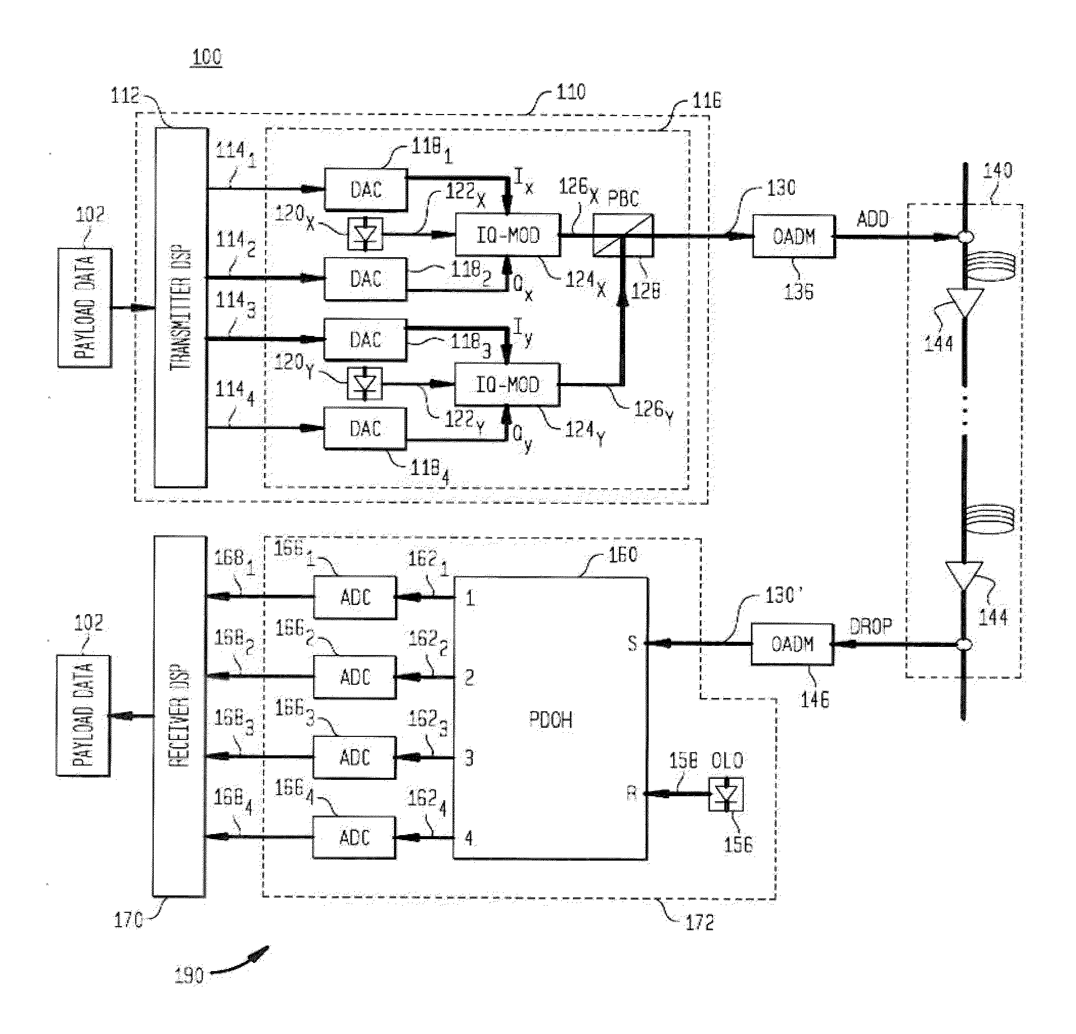
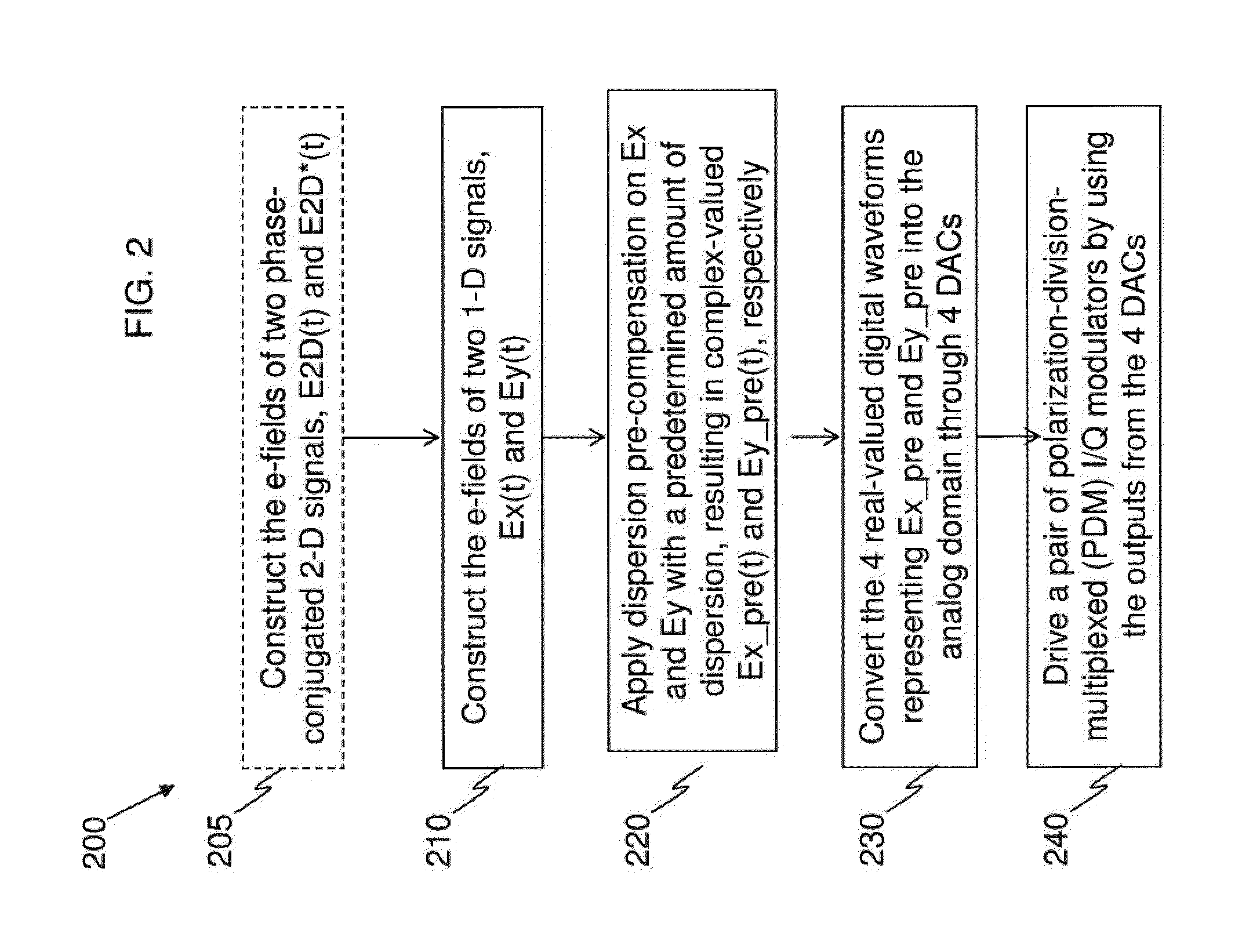
[0010]Accordingly, provided herein are methodologies in which (1) a pair of multiplexed 1-Dimensional signals (M-1DS) are generated, which may be generated by performing an unitary transform on a PCTW; (2) a pre-determined amount of dispersion is added on the components of the M-1DS, such that the power-weighted dispersion distribution (PWDD) function of the transmission link is centered near zero; (3) the pre-dispersion-compensated M-1DS (PreC-M-1DS) are transmitted over an optical transmission link; (4) and coherently detected at an optical receiver; and (5) the data carried by the M-1D is recovered. The M-1DS can be multiplexed via polarization-division multiplexing (PDM), wavelength-division multiplexing (WDM), o

Problems solved by technology

The cost of this reduction is a concomitant increase in the required forward-channel bandwidth, the latter being dependent on the overhead of the FEC code.
However, one problem with FEC coding, as applied to optical transmission systems, is that the coding-gain differences among various implementable FEC codes usually do not exceed a certain maximum value, as given by Shannon's information capacity theory.
In long-haul optical fiber transmission, fiber nonlinear effects further limit the transmission performance.
In addition, the digital signal processing (DSP) complexity for capacity-approaching FEC codes can be forbiddingly high.
Digital nonlinear compensation usually requires high digi

Method used


Image

  • Communication through multiplexed one-dimensional optical signals
  • Communication through multiplexed one-dimensional optical signals
  • Communication through multiplexed one-dimensional optical signals

Examples


Embodiment Construction

[0042]Illustrative embodiments are described below. In the interest of clarity, not all features of an actual implementation are described in this specification. It will of course be appreciated that in the development of any such actual embodiment, numerous implementation-specific decisions should be made to achieve the developers' specific goals, such as compliance with system-related and business-related constraints, which will vary from one implementation to another. Moreover, it will be appreciated that such a development effort might be complex and time-consuming, but would nevertheless be a routine undertaking for those of ordinary skill in the art having the benefit of this disclosure. The description and drawings merely illustrate the principles of the claimed subject matter. It should thus be appreciated that those skilled in the art may be able to devise various arrangements that, although not explicitly described or shown herein, embody the principles described herein an...


PUM


Abstract

An example apparatus comprises an optical transmitter which includes a first processor and at least two optical modulators. The first processor is configured to generate a first electronic representation for each of at least two optical signals for carrying payload data modulated according to a one-dimensional (1-D) modulation format, and to induce on respective ones of the first electronic representations an amount of dispersion that depends on a power-weighted accumulated dispersion (ADPW) of a transmission link through which the at least two optical signals are to be transmitted thereby generating complex-valued electronic representations of pre-dispersion-compensated optical signals. Each of the at least two optical modulators modulate a respective analog version corresponding to a respective one of the complex-valued electronic representations onto a polarization of an optical carrier.

Description

CROSS-REFERENCE TO RELATED APPLICATIONS[0001]This application is a continuation-in-part of U.S. patent application Ser. No. 13 / 601326, filed Aug. 31, 2012, which is continuation-in-part of U.S. patent application Ser. No. 13 / 411462, filed Mar. 2, 2012, which is a continuation-in-part of U.S. patent application Ser. No. 13 / 245160, filed Sep. 26, 2011, which claims the benefit of U.S. Provisional Patent Application No. 61 / 535,548, filed Sep. 16, 2011, all of which are incorporated herein by reference in their entirety.FIELD[0002]The invention(s) relate to optical communication equipment and, more specifically but not exclusively, to equipment for managing data transport through a nonlinear and / or noisy optical channel.DESCRIPTION OF THE RELATED ART[0003]This section introduces aspects that may help facilitate a better understanding of the invention(s). Accordingly, the statements of this section are to be read in this light and are not to be understood as admissions about what is in t...

Claims


Application Information

Patent Timeline
IPC IPC(8): H04B10/2507
CPCH04B10/2507H04B10/5053H04B10/516H04B10/25137
Inventor LIU, XIANGWINZER, PETER J.CHRAPLYVY, ANDREW R.TKACH, ROBERT W.SETHUMADHAVAN, CHANDRASEKHAR
Owner WSOU INVESTMENTS LLC
Why Eureka
Try Eureka