Method for fabricating buried gates using pre landing plugs
a technology of buried gates and plugs, which is applied in the direction of semiconductor devices, electrical equipment, basic electric elements, etc., can solve the problems of increased gidl (gate induced drain leakage) between the storage node contact and the buried gate, and the possibility of causing a self-aligning contact to fail,
- Summary
- Abstract
- Description
- Claims
- Application Information
AI Technical Summary
Benefits of technology
Problems solved by technology
Method used
Image
Examples
first embodiment
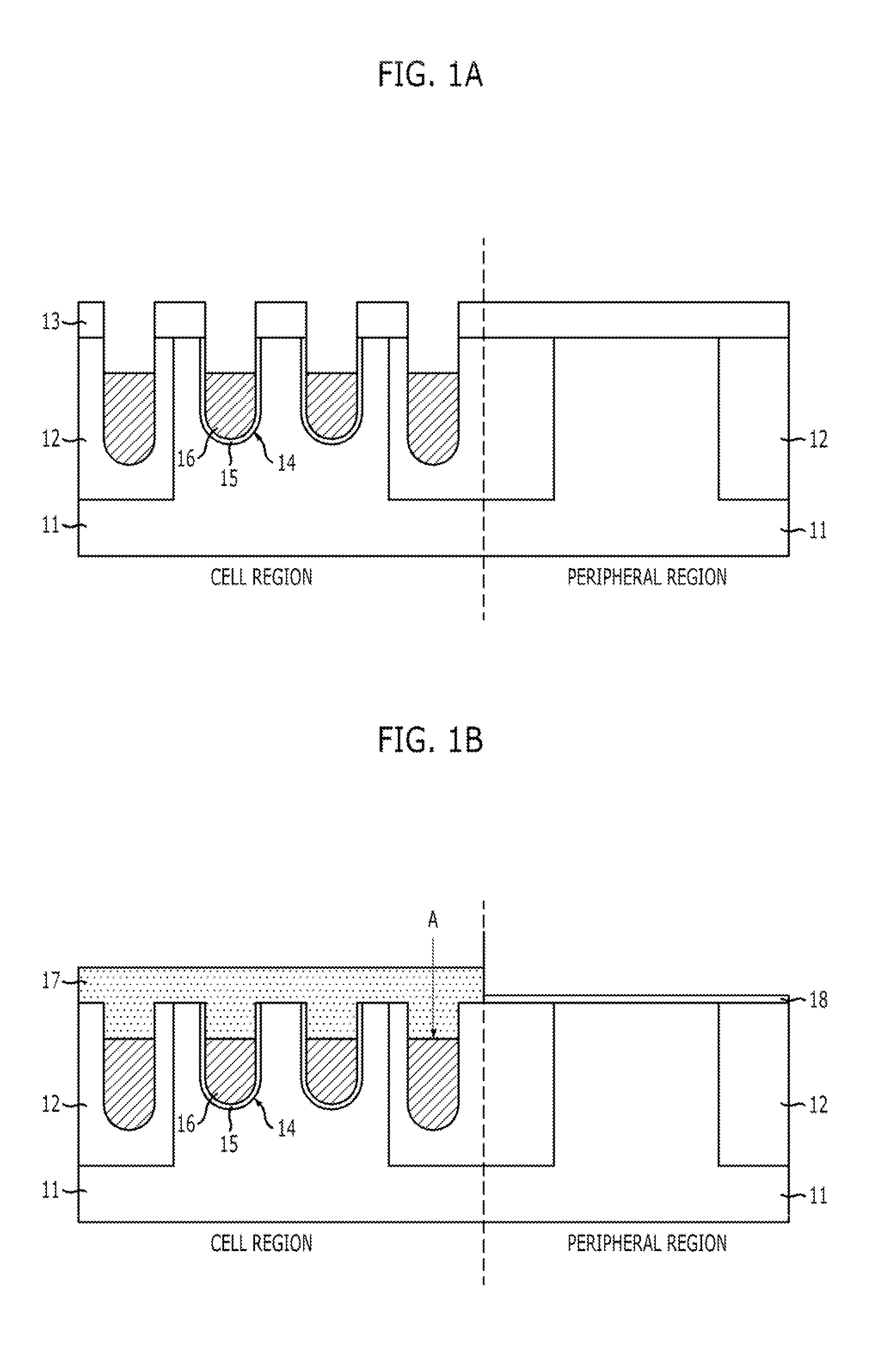
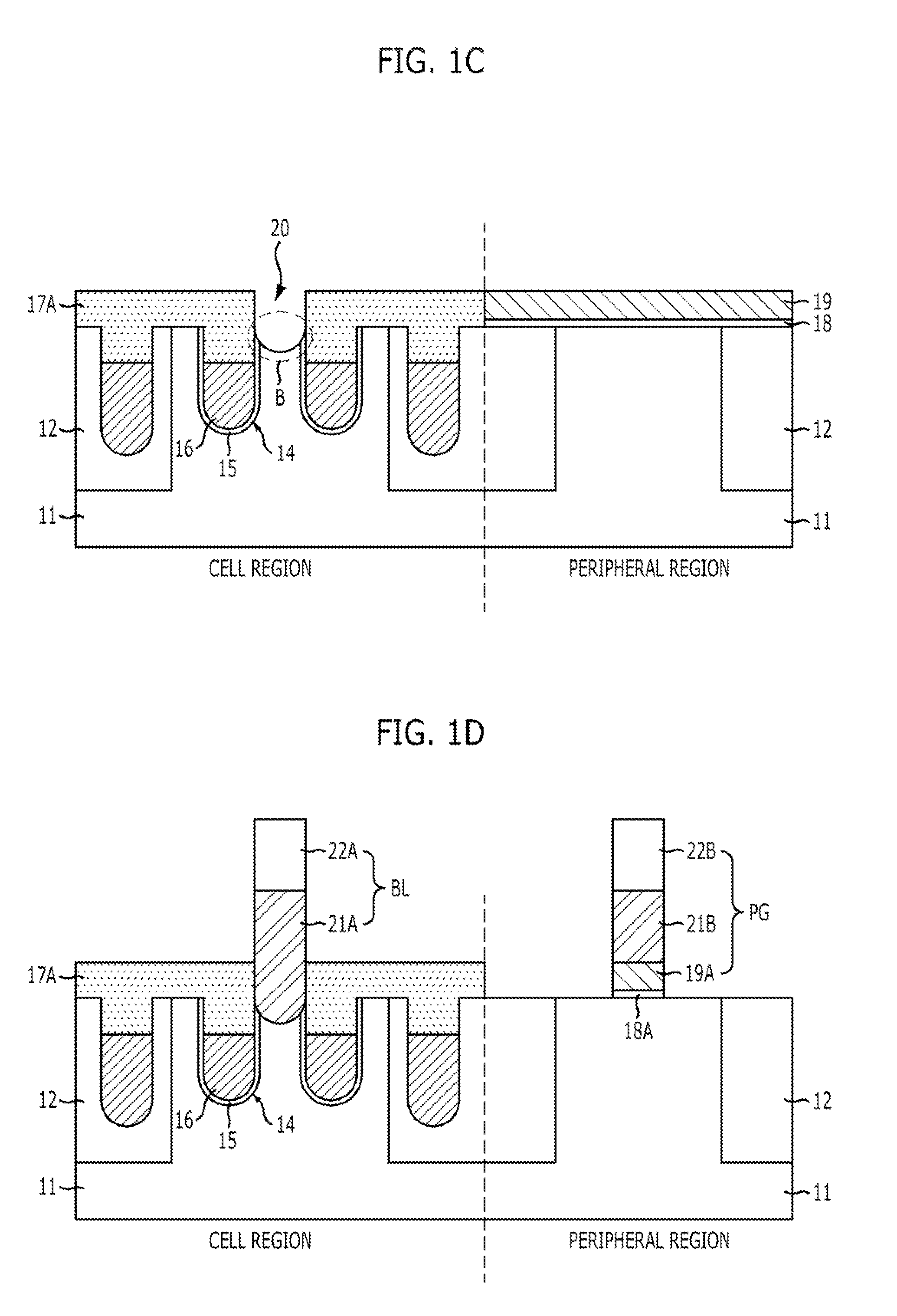
[0036]FIGS. 2A to 2H are cross-sectional views illustrating a method for fabricating a semiconductor device, in accordance with a
[0037]Referring to FIG. 2A, a substrate 31 is etched by using a structure stacked in the order of a pad oxide layer 32A and a first hard mask layer 32B to form a first trench 33, where a device isolation layer is being formed. Here, the first hard mask layer 32B may include a polysilicon layer or a nitride layer. Preferably, the first hard mask layer 32B may have a stack structure of a polysilicon layer and a nitride layer.
[0038]Referring to FIG. 2B, a device isolation layer 34 gap-filling the first trench 33 (see FIG. 2A) is formed. The above process of forming the device isolation layer 34 is called ‘STI (Shallow Trench Isolation)’ process, and the device isolation layer 34 is formed by forming the first trench 33, and then gap-filling the first trench 33 with an insulating layer.
[0039]Referring to FIG. 2C, the first hard mask layer 32A (see FIG. 2B) and...
second embodiment
[0048]FIGS. 3A to 3F are cross-sectional views illustrating a method for fabricating a semiconductor device in accordance with a
[0049]Referring to FIG. 3A, a plug conductive layer is formed on an entire surface of a substrate. The plug conductive layer includes a polysilicon layer, and is formed in a thickness range of 600-1500 {hacek over (A)}, although other thickness ranges are contemplated. Also, the plug conductive layer may include a metal layer such as a tungsten layer, or the like.
[0050]Next, a hard mask layer is formed on the plug conductive layer, and then an STI (Shallow Trench Isolation) process is performed. That is, the hard mask layer is etched by using a device isolation mask (not shown) and then the plug conductive layer and the substrate are etched to form a first trench 44 having a predetermined depth at a portion serving as a device isolation layer. The hard mask layer 43 may include a nitride layer. FIG. 3A illustrates a substrate 41 having a first trench 44, a ...
third embodiment
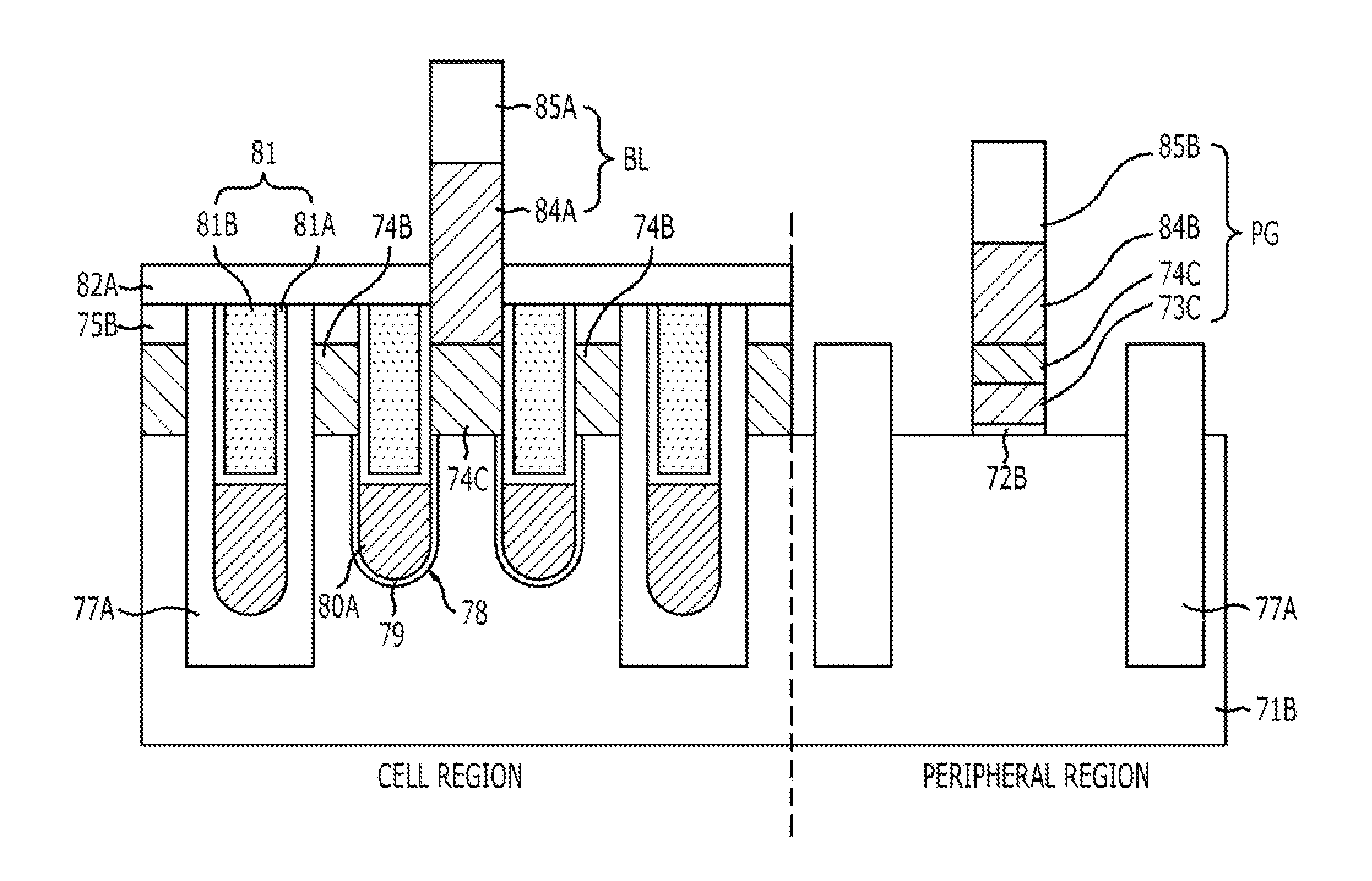
[0061]FIGS. 4A to 4J are cross-sectional views illustrating a method for fabricating a semiconductor device, according to a
[0062]Referring to FIG. 4A, a first trench 53 is formed through an etch process using a first hard mask layer 52B in a substrate 51, where a cell region and a peripheral region are defined. The first hard mask layer 52B may include a polysilicon layer or a nitride layer. Preferably, the first hard mask layer 52B may have a stack structure of a polysilicon layer and a nitride layer. A pad oxide layer 52A is formed below the first hard mask layer 52B.
[0063]Thereafter, a device isolation layer 54 for gap-filling the first trench 53 is formed. This process of forming the device isolation layer 54 is called ‘STI (Shallow Trench Isolation)’ process, and the device isolation layer 34 is formed by forming the first trench 53, and then gap-filling the first trench 53 with an insulating layer, such as an HDP layer, an SOD layer, or the like.
[0064]Referring to FIG. 4B, the...
PUM
 Abstract
Description
Claims
Application Information
 - R&D
- Intellectual Property
- Life Sciences
- Materials
- Tech Scout
- Unparalleled Data Quality
- Higher Quality Content
- 60% Fewer Hallucinations
Browse by: Latest US Patents, China's latest patents, Technical Efficacy Thesaurus, Application Domain, Technology Topic, Popular Technical Reports.
© 2025 PatSnap. All rights reserved.Legal|Privacy policy|Modern Slavery Act Transparency Statement|Sitemap|About US| Contact US: help@patsnap.com


