Method and apparatus for sensing magnetic fields

a magnetic field and sensing device technology, applied in the direction of electrical/magnetically converting the output of the sensor, instruments, magnetic property measurements, etc., can solve the problems of high demands on the precision of printing or etching process, low detection accuracy, and disadvantages of the prior art sensing devi

Inactive Publication Date: 2013-06-06
MICRO EPSILON MESSTECHNIK GMBH & CO KG
View PDF2 Cites 10 Cited by
  • Summary
  • Abstract
  • Description
  • Claims
  • Application Information

AI Technical Summary

Benefits of technology

[0036]If at the location of the wire an external magnetic field is applied, the relative permeability of the wire changes, by the permeability reducing with an increasing field. This way the skin-depth increases, which leads to the current also flowing in the lower layers underneath the wire surface. Thus, the effective wire cross-section increases, resulting in the resistance and / or the impedance Z reducing.
[0037]The size of the GMI-effect is measured in the relative change of impedanceΔZZ=Z(H)-Z(Hs)Z(Hs)with Z(H) representing the impedance in the magnetic field H and Z(Hs) the impedance in the saturation field strength Hs. The relative change is particularly strong in thin films or wires, because the skin-depth here shows a relative large portion in reference to the overall thickness or diameter. This relative change can assume very high values, allowing to produce very sensitive magnetic field sensors.

Problems solved by technology

The sensors of prior art show disadvantages, though:
Coils are relatively expensive components, because they are difficult to wind or, in case of coils printed or etched on circuit boards, set high demands to the precision of the printing or etching process.
Another disadvantage of such sensors is the fact that coils or magnetic cores represent relatively large-volume parts.
Thus, it is not possible with these principles to produce small, compact sensors which can also be used in restricted construction spaces.
Another disadvantage of the sensors of prior art is the fact that they measure primarily the strength of the magnetic field H. For example, in Hall-sensors of prior art there is a direct linear connection between the measuring signal, namely the Hall-voltage UH and the magnetic field H. Even in the magneto-resistive sensors the primary measuring signal is proportional to the magnetic field H. Thus, the magnetic field can be measured very well with these types of sensors.
A serious disadvantage is given here, though, in that the magnetic field of a permanent magnet or an electromagnet is not reducing linearly with increasing distance from the magnet but shows an extremely non-linear (frequently exponentially) reducing parameter, which is known per se.
However, this method drastically restricts the measuring range available.

Method used


Image

  • Method and apparatus for sensing magnetic fields
  • Method and apparatus for sensing magnetic fields
  • Method and apparatus for sensing magnetic fields

Examples


Embodiment Construction

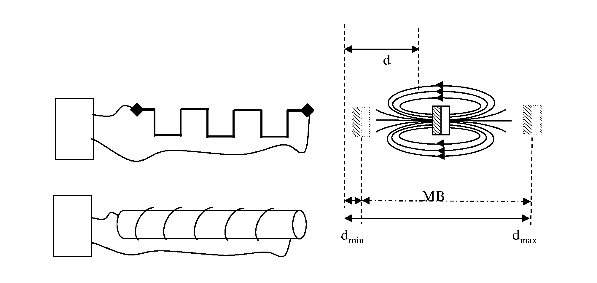
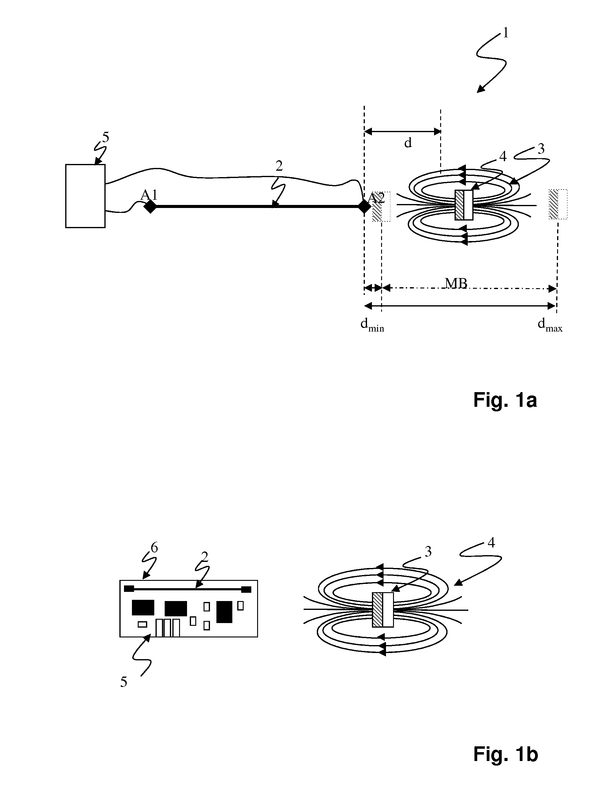
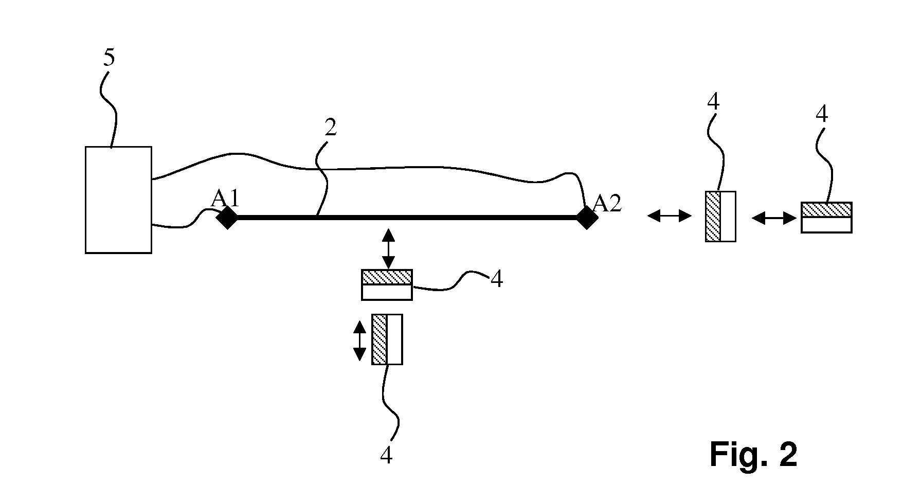
[0058]The sensor according to the invention may comprise an oblong, soft-magnetic material connected to electronics and flown-through by alternating current. A magnet is allocated to the measuring object, which magnet changes the permeability in the soft-magnetic material depending on the position of the measuring object in reference to the sensor (see FIGS. 1a, 1b).

[0059]By changing the permeability, the complex impedance of the circuit changes due to the GMI-effect, which is formed by the soft-magnetic material. In the following, the soft-magnetic material is called the base element, for reasons of simplification. It is beneficial to evaluate the relative change in impedance.

[0060]The evaluation of the impedance using methods of prior art makes it possible to therefore determine the position of the measuring object in reference to the sensor. For example, the impedance can be measured by detecting the voltage drop over the wire, from which then conclusions can be drawn regarding t...


PUM


Abstract

A method for detecting magnetic fields, particularly for detecting the position of objects with a preferably oblong, soft-magnetic element, which is connected to electronics, with via the electronics the impedance of the soft-magnetic material is measured, characterized in that a magnetic field is used in which by the position of an object which is located in an arrangement with the soft-magnetic material the magnetic field develops at the location of the soft-magnetic material, with the magnetic permeability μ of the soft-magnetic material adjusting, depending on the magnetic field and thus the position of the object. A respective device serves for applying the method according to the invention.

Description

CROSS REFERENCE TO RELATED APPLICATIONS[0001]This application is a National Stage application, filed under 35 U.S.C. §371, of International Application PCT / DE2011 / 001590, filed Aug. 12, 2011, which claims priority to German Application No. 10 2010 034 327.7, filed Aug. 14, 2010, both of which are hereby incorporated by reference in their entirety.BACKGROUND[0002]1. Technical Field[0003]The invention relates to a method and a device for detecting magnetic fields, particularly for detecting the position of objects. Concretely, the invention relates to a method for detecting magnetic fields, particularly for detecting the position of objects, with a preferably oblong, soft-magnetic element, which is connected to electronics, with the impedance of the soft-magnetic material being measured via electronics. Furthermore, the invention relates to a device for detecting magnetic fields, particularly for detecting the position of objects, with a preferably oblong, soft-magnetic material, whic...

Claims


Application Information

Patent Timeline
Patent Type & Authority Applications(United States)
IPC IPC(8): G01B7/14
CPCG01D5/14G01B7/14G01R33/1223
Inventor PFAFFINGER, CHRISTIANHOFER, JOHANNMEDNIKOV, FELIXWISSPEINTNER, THOMASSCHALLMOSER, GUENTER
Owner MICRO EPSILON MESSTECHNIK GMBH & CO KG
Why Eureka
Try Eureka