Method and apparatus to eliminate fuel use for electric drive machines during trolley operation

Active Publication Date: 2013-06-13
CATERPILLAR INC
View PDF11 Cites 14 Cited by
  • Summary
  • Abstract
  • Description
  • Claims
  • Application Information

AI Technical Summary

Benefits of technology

[0010]In yet another aspect of the disclosure, a method for eliminating fuel consumption during trolley propel and dynamic braking of an electric drive machine is disclosed. The machine includes at least an engine coupled to a generator, a motor operatively coupled to drive wheels, and auxiliary devices. The method provides an inverter circuit in electrical communication between the generator and the motor as well as an auxiliary driver in electro-mechanical communication between the generator and the auxiliary devices. The method further determines a current mode

Problems solved by technology

Although such storage configurations may reduce fuel consumption during retarding modes, the extra weight added to the vehicle may in fact increase fuel consumption during propel modes.
Implementing storage configurations also introduces significant cost and technological limitations, among other things.
However, retarding grid configurations introduce several control limitations.
Among other things, these configurations prohibit operation of the grid cooling system without providing significant braking force.
More specifically, because the grid cooling system is powered only by waste energy that is supplied by the motor during retarding modes, the grid cooling system is unable to operate once the machine exits the retarding mode without absorbing a prohibitively large amount of power from the engine and

Method used


Image

  • Method and apparatus to eliminate fuel use for electric drive machines during trolley operation
  • Method and apparatus to eliminate fuel use for electric drive machines during trolley operation
  • Method and apparatus to eliminate fuel use for electric drive machines during trolley operation

Examples


Embodiment Construction

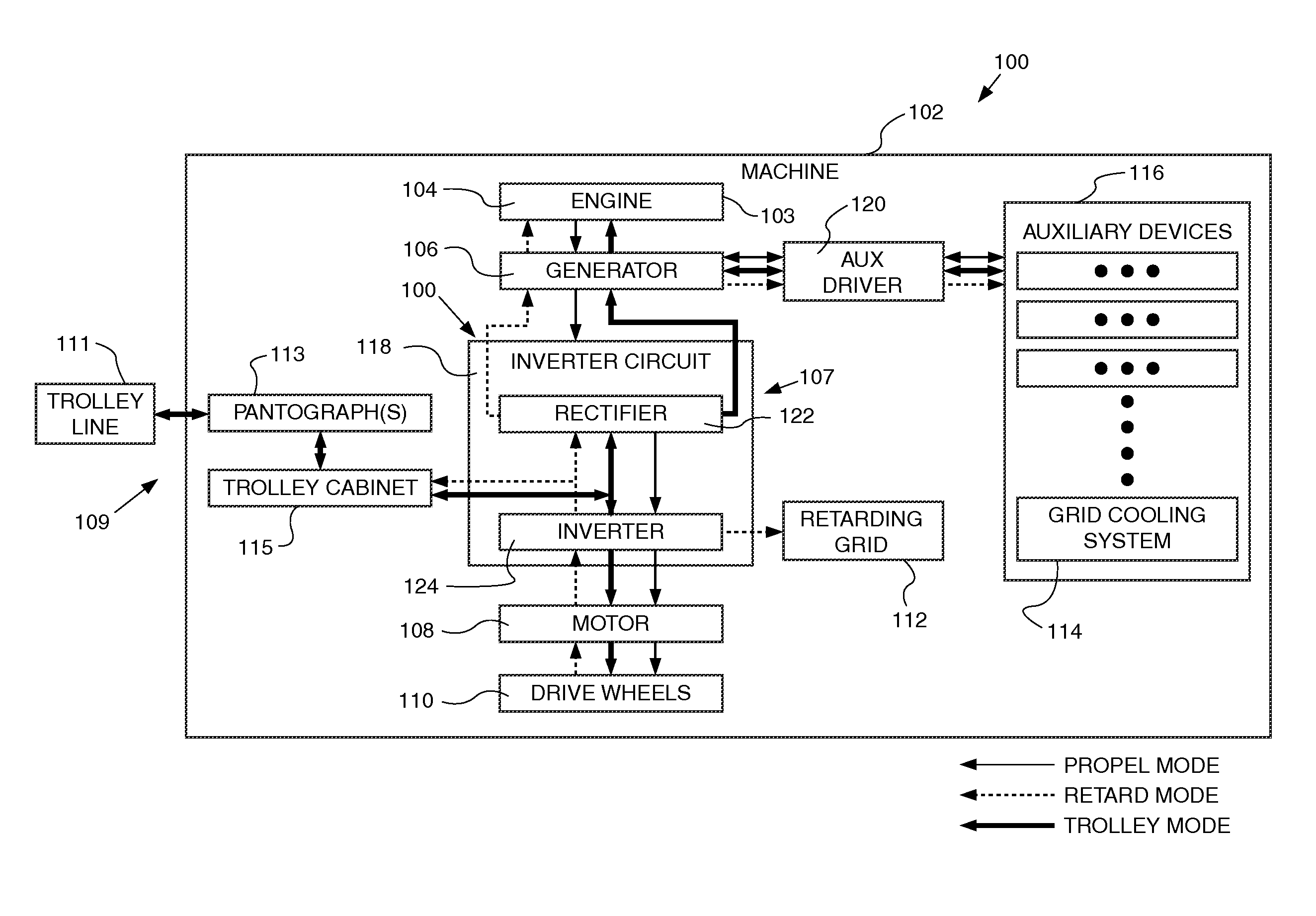
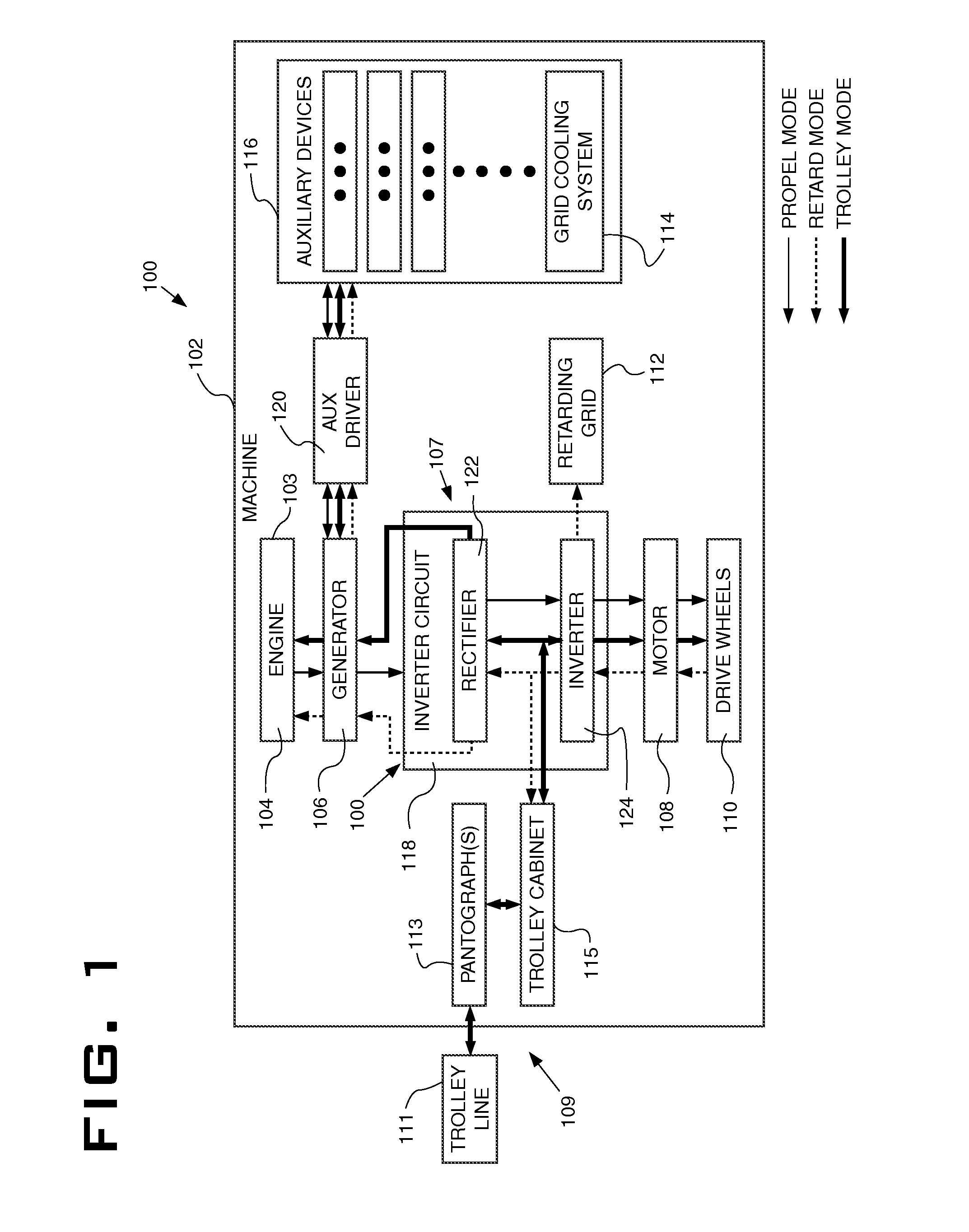
[0021]Referring to FIG. 1 schematically illustrates an exemplary drive system 100 as applied to a machine 102, such as for example an electric drive off-road truck. The machine 102 typically includes a prime mover 103 such as an internal combustion engine 104, a generator 106, power electronics 107, one or more motors 108, one or more wheels 110, a retarding grid 112, a grid cooling system 114 and one or more auxiliary devices 116. In this example, drive system 100 also involves a trolley drive arrangement 109 such as a trolley lines 111 which includes two overhead lines as is recognized in the industry but are not shown. It should be noted here that the trolley lines 111 may be provided to propel the machine in an up hill direction, or a down hill direction depending on where the load and dump locations are positioned. The trolley drive arrangement 109 also includes a pantograph(s) 113 positioned on the machine to connect to the trolley lines 111, and a trolley cabinet 115 interfac...


PUM


Abstract

A drive system for a machine having an engine, a generator, a trolley drive arrangement, a motor, wheels and auxiliary devices is provided. The drive system includes an inverter circuit and an auxiliary driver both being operatively connected to the trolley drive arrangement. The inverter circuit may be coupled to each of the generator and the motor. The auxiliary driver may be coupled to each of the generator and the auxiliary devices. The inverter circuit and the auxiliary driver may be configured to automatically communicate power from the trolley drive arrangement and any power from the auxiliary devices to the motor in a trolley propel mode, and automatically communicate power from the motor to the engine, the trolley drive arrangement, and optionally to a hybrid system if applicable, in a dynamic braking mode, while attached to trolley lines so as to eliminate fuel consumption while attached to the trolley lines.

Description

TECHNICAL FIELD[0001]The present disclosure relates generally to the operation of electric drive machines, and more particularly, to systems and methods that eliminate fuel consumption during trolley operation and dynamic brakingBACKGROUND[0002]Electric drive systems for machines typically include a power circuit that selectively activates at least one motor at a desired torque. The motor is typically connected to a wheel or other traction device that operates to propel the machine. An electric drive system includes a prime mover, for example, an internal combustion engine that drives a generator. The generator produces electrical power that is used to drive the motor. When the machine is propelled, mechanical power produced by the engine is converted to electrical power at the generator. This electrical power is often processed and / or conditioned before being supplied to the motor. The motor transforms the electrical power back into mechanical power to drive the wheels and propel t...

Claims


Application Information

Patent Timeline
IPC IPC(8): B60L9/00B60L11/02B60L50/10B60L50/16
CPCY02T10/7077Y02T90/16B60L11/123Y02T10/6217Y02T10/7005B60L50/61Y02T10/62Y02T10/7072Y02T10/70
Inventor HENDRICKSON, MATTHEWGILMORE, DONALDRUTH, ERIC
Owner CATERPILLAR INC
Why Eureka
Try Eureka