
Display substrate and method of manufacturing the same

a technology of display substrate and substrate, applied in the field of display substrate, can solve the problems of over-etching, uniform polarization pattern, and defect of the photoresist pattern itself, and achieve the effect of improving the productivity of forming the display substra

Active Publication Date: 2013-06-13
SAMSUNG DISPLAY CO LTD
View PDF2 Cites 17 Cited by
  • Summary
  • Abstract
  • Description
  • Claims
  • Application Information

AI Technical Summary

Benefits of technology

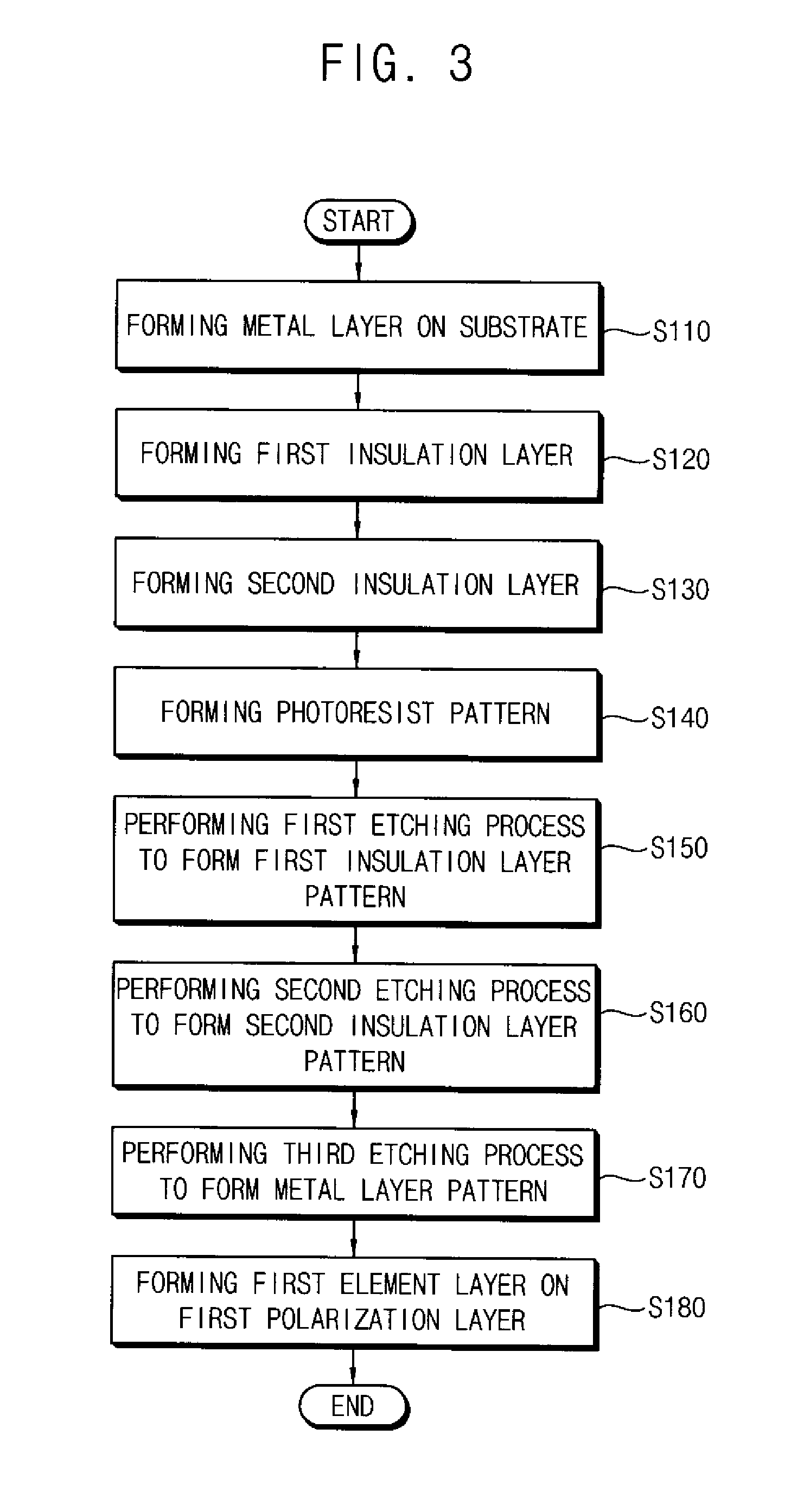
The invention provides a display substrate with minimal defects and improved productivity during the formation of a polarization pattern. This is achieved by detecting the intensity of carbon-nitride light during the etching process and stopping it when it exceeds a reference range. Additionally, the metal layer is formed with two sub-layers to prevent deformation of the first sub-layer. This results in a reduced likelihood of defects and minimizes reaction product material, improving productivity.

Problems solved by technology

However, the manufacturing method of the polarization layer described above may generate the following problems.
Generally, when an etching process is performed, an over-etching may be generated where about 30% more of a thin layer is undesirably removed.
However, when a thickness of the photoresist is not sufficient, a mask which is formed by a lower layer is blocked due to an over-etching process, so that the finally formed polarization pattern is not uniform.
That is, a defect of the photoresist pattern itself may be generated.

Method used


Image

  • Display substrate and method of manufacturing the same
  • Display substrate and method of manufacturing the same
  • Display substrate and method of manufacturing the same

Examples


Embodiment Construction

[0045]It will be understood that when an element or layer is referred to as being “on” or “coupled to” another element or layer, the element or layer can be directly on or coupled to another element or layer or intervening elements or layers. In contrast, when an element is referred to as being “directly on” or “directly coupled to” another element or layer, there are no intervening elements or layers present. As used herein, connected may refer to elements being physically and / or electrically connected to each other. Like numbers refer to like elements throughout. As used herein, the term “and / or” includes any and all combinations of one or more of the associated listed items.

[0046]It will be understood that, although the terms first, second, third, etc., may be used herein to describe various elements, components, regions, layers and / or sections, these elements, components, regions, layers and / or sections should not be limited by these terms.

[0047]These terms are only used to dist...


PUM

PropertyMeasurementUnit
distanceaaaaaaaaaa
thickness W2aaaaaaaaaa
widthaaaaaaaaaa

Abstract

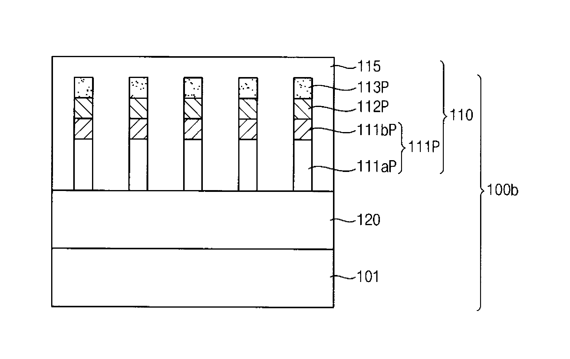
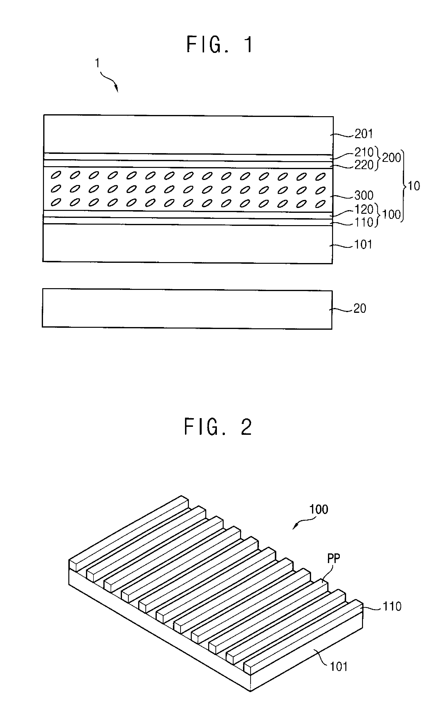
A display substrate includes a metal pattern, a first insulation layer pattern and a second insulation layer pattern. The metal pattern is on a base substrate. The first insulation pattern is on the metal pattern and includes one of a silicon nitride (SiNx) and a silicon oxide (SiOx). The second insulation pattern is on the first insulation pattern and includes a remaining one of the silicon nitride (SiNx) and the silicon oxide (SiOx).

Description

[0001]This application claims priority to Korean Patent Application No. 10-2011-0130258, filed on Dec. 7, 2011, and all the benefits accruing therefrom under 35 U.S.C. § 119, the contents of which are herein incorporated by reference in their entirety.BACKGROUND OF THE INVENTION[0002]1. Field of the Invention[0003]Exemplary embodiments of the invention relate to a display substrate and a method of manufacturing the display substrate. More particularly, exemplary embodiments of the invention relate to a display substrate including a polarization pattern and a method of manufacturing the display substrate.[0004]2. Description of the Related Art[0005]Generally, a liquid crystal display (“LCD”) device including liquid crystals further includes a polarization layer disposed on a rear surface and an upper surface of an LCD panel, so that the liquid crystals may function as a light shutter.[0006]A polarization film is mainly used as the polarization layer. The polarization layer may includ...

Claims


Application Information

Patent Timeline
Patent Type & Authority Applications(United States)
IPC IPC(8): H01L33/08
CPCG02F1/1333G02F2001/133548G02F2001/133545G02F1/133528G02F1/133545G02F1/133548G02B5/30G02F1/1335
Inventor RYU, YONG-HWANCHOI, SHIN-ILPARK, HONG-SICK
Owner SAMSUNG DISPLAY CO LTD
Learn More