
Enhanced bandwidth transducer for well integrity measurement

Inactive Publication Date: 2013-06-13
PIEZO TECH
View PDF4 Cites 7 Cited by
  • Summary
  • Abstract
  • Description
  • Claims
  • Application Information

AI Technical Summary

Benefits of technology

The patent describes a way to connect two pieces of ceramic together, using lead wires. This connection allows for a wider range of frequencies that can be transmitted between the ceramics. The ceramics can be driven either individually or in groups, and the connection scheme helps achieve a wide bandwidth. Overall, this technology allows for more efficient and effective communication between the ceramics.

Problems solved by technology

If there is a problem with cement bond quality, the integrity of the well may be compromised and the problem must be fixed.
Moreover, during the life of the well, problems such as deterioration of the cement bond quality as well as with the metal casing may cause the integrity of the well to be compromised.
While current technology provides various manners of non-destructive determining of well integrity, pressure and temperature considerations, particularly in deep wells (e.g. −180° C. and 20,000 psi), limits the type of technology utilized both functionally and economically.
However, because of space and cost considerations of well tools the number of piezoelectric transducers is limited.
As such, current well tools do not have the capability to cover the large bandwidth necessary to perform well integrity analysis on a sizable range of metal casing thicknesses.
What is therefore needed is a compact single acoustic device that covers a large bandwidth particularly, but not necessarily for well integrity measurements.

Method used


Image

  • Enhanced bandwidth transducer for well integrity measurement
  • Enhanced bandwidth transducer for well integrity measurement
  • Enhanced bandwidth transducer for well integrity measurement

Examples


Embodiment Construction

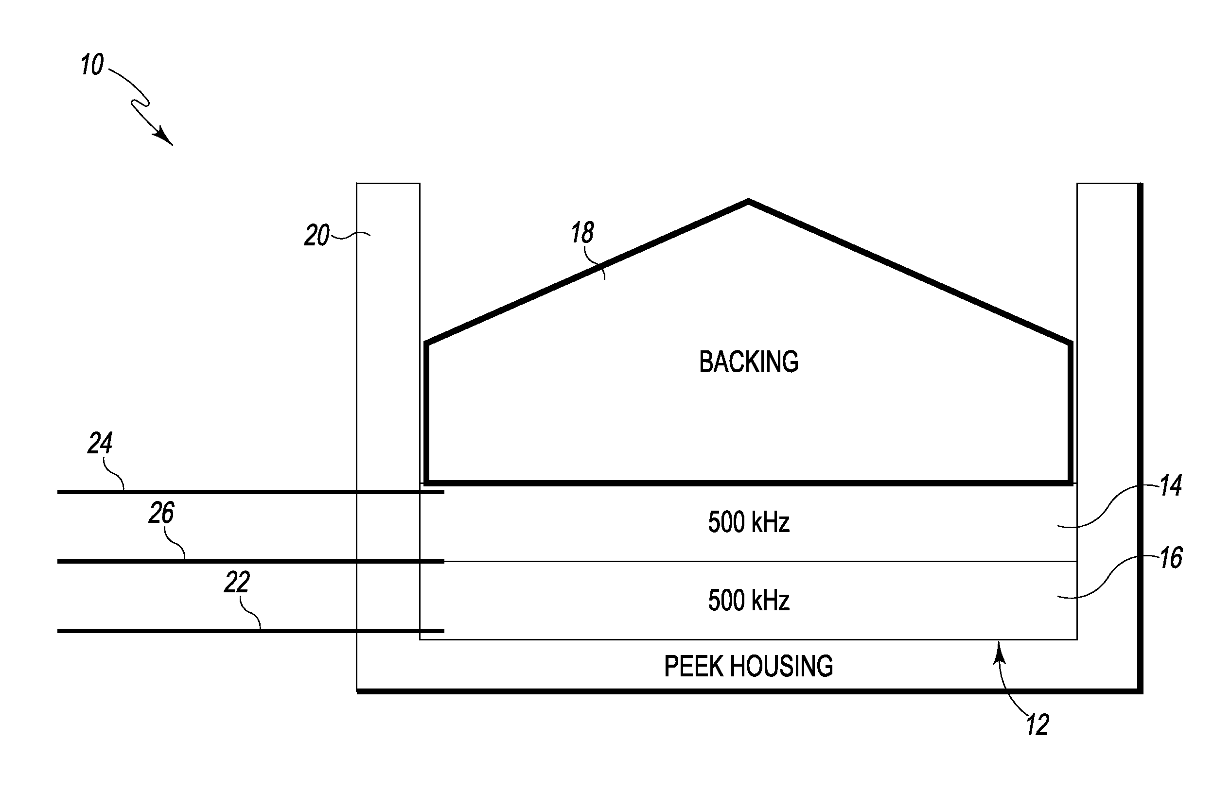
[0033]Referring to FIG. 1, there is depicted a critically damped acoustic transducer (“acoustic transducer”), generally designated 10, fashioned in accordance with the present principles. The acoustic transducer 10 has an acoustic stack 12 having two (arbitrarily, first and second) acoustic elements 14, 16. It should be appreciated that while only two acoustic elements are shown, the acoustic stack 12 may consist of two or more (i.e. a plurality) of acoustic elements. The acoustic elements are preferably piezoelectric ceramics, however, other types of acoustic elements may be used. The acoustic stack 12 may be fashioned as an acoustic transducer or as only an acoustic transmitter depending on its electrical connection. Thus, description of the acoustic stack 12 and its components are applicable to the embodiment as a transducer 10 or as an acoustic transmitter except as indicated.

[0034]The acoustic elements 14, 16 are bonded to each other while the acoustic stack 12 is mounted to a ...


PUM


Abstract

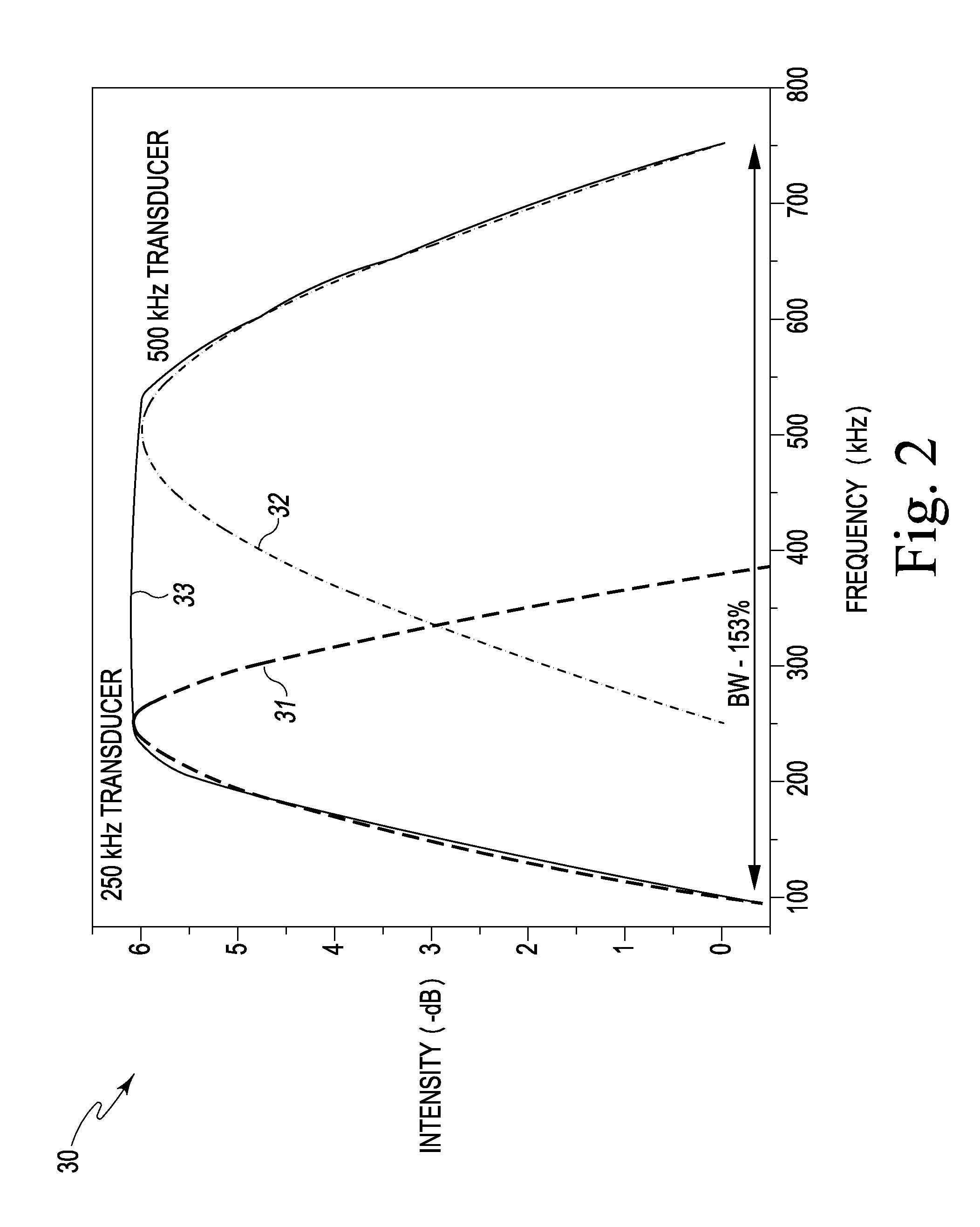
A single critically damped acoustic stack yields a wide frequency range as an acoustic transmitter or as an acoustic transducer having particular use in well integrity determination. The critically damped present acoustic stack utilizes a plurality of stacked acoustic elements such as piezoelectric ceramics that are energized in two manners, providing different center frequencies; each producing a respective center frequency of 100% bandwidth to yield an acoustic stack having a total bandwidth exceeding the bandwidth of an acoustic element or the bandwidth of the plurality of acoustic elements. One manner of energizing is to pulse only one of the acoustic elements. The other manner is to pulse a first acoustic element the pulse a second acoustic element after a delay equal to the amount of time it takes for the first pulse to reach the face of the second acoustic element. The acoustic elements are bonded together and onto a critically damped backing of tungsten. The assembly is retained in a housing that is preferably made of PEEK. The acoustic stack is primarily used in pulse-echo analysis of metal casing wall thickness and cement bond quality detection of wells.

Description

CROSS-REFERENCE TO RELATED APPLICATIONS[0001]This U.S. non-provisional patent application claims the benefit of and priority to U.S. provisional patent application Ser. No. 61 / 569,872 filed Dec. 13, 2011 entitled Enhanced Bandwidth Transducer For Well Integrity Measurement, the entire contents of which is specifically incorporated herein by reference.FIELD OF THE INVENTION[0002]The present invention relates to the field of acoustic measurement devices and, more particularly, to devices for measuring well integrity.BACKGROUND[0003]During formation of a well, a hole is drilled in the earth and a metal casing is inserted into the hole. After the metal casing is in place, cement is used to fill in the area between the metal casing and the wall of the hole. It is important for the integrity of the well that the cement properly cure, create a solid bond between the outside of the metal casing and the wall of the hole, and be free of voids and / or air pockets—together known as cement bond q...

Claims


Application Information

Patent Timeline
IPC IPC(8): H01L41/083H01L41/09
CPCH01L41/083H01L41/09E21B47/16H01L41/1132E21B47/091B06B1/0614E21B47/095B06B1/0215G01B17/02H04B11/00E21B47/005H10N30/20H10N30/50
Inventor MATAM, MAHESHLAUTZENHISER, FRANSGWIN, PAT
Owner PIEZO TECH
Learn More