Antenna device and communication terminal apparatus

a technology of communication terminal and antenna device, which is applied in the direction of resonant antenna, loop antenna with ferromagnetic core, protective material radiating elements, etc., can solve the problems of low position accuracy between the magnetic body and the antenna coil, affecting the electric characteristics of the antenna device, and complicated manufacturing process. , to achieve the effect of simple process

Active Publication Date: 2013-06-13
MURATA MFG CO LTD
View PDF2 Cites 38 Cited by
  • Summary
  • Abstract
  • Description
  • Claims
  • Application Information

AI Technical Summary

Benefits of technology

[0020]According to various preferred embodiments of the present invention, an antenna device that can be manufactured by a simple process, has characteristics that do not vary widely, and has satisfactory characteristics, and a communication terminal apparatus including the antenna device is provided.

Problems solved by technology

In such an antenna device, however, because it has a structure in which the antenna coil has an opening in its central portion and a bar-shaped magnetic body (flat-shaped magnetic core member) is disposed in this opening, its manufacturing process is complicated.
Thus, the positional accuracy between the magnetic body and the antenna coil is low and the characteristics of an obtained antenna device tend to widely vary.
In addition, an adhesive for use in fixing the antenna coil and the plate-shaped magnetic body is needed, and the adhesive may negatively affect the electric characteristics of the antenna device, depending on the type or applied amount of the adhesive.
Thus, there is a problem in that a magnetic flux is reflected on the interface between the magnetic body and a dielectric body (non-magnetic body) and the magnetic-field coupling decreases.

Method used


Image

  • Antenna device and communication terminal apparatus
  • Antenna device and communication terminal apparatus
  • Antenna device and communication terminal apparatus

Examples


first preferred embodiment

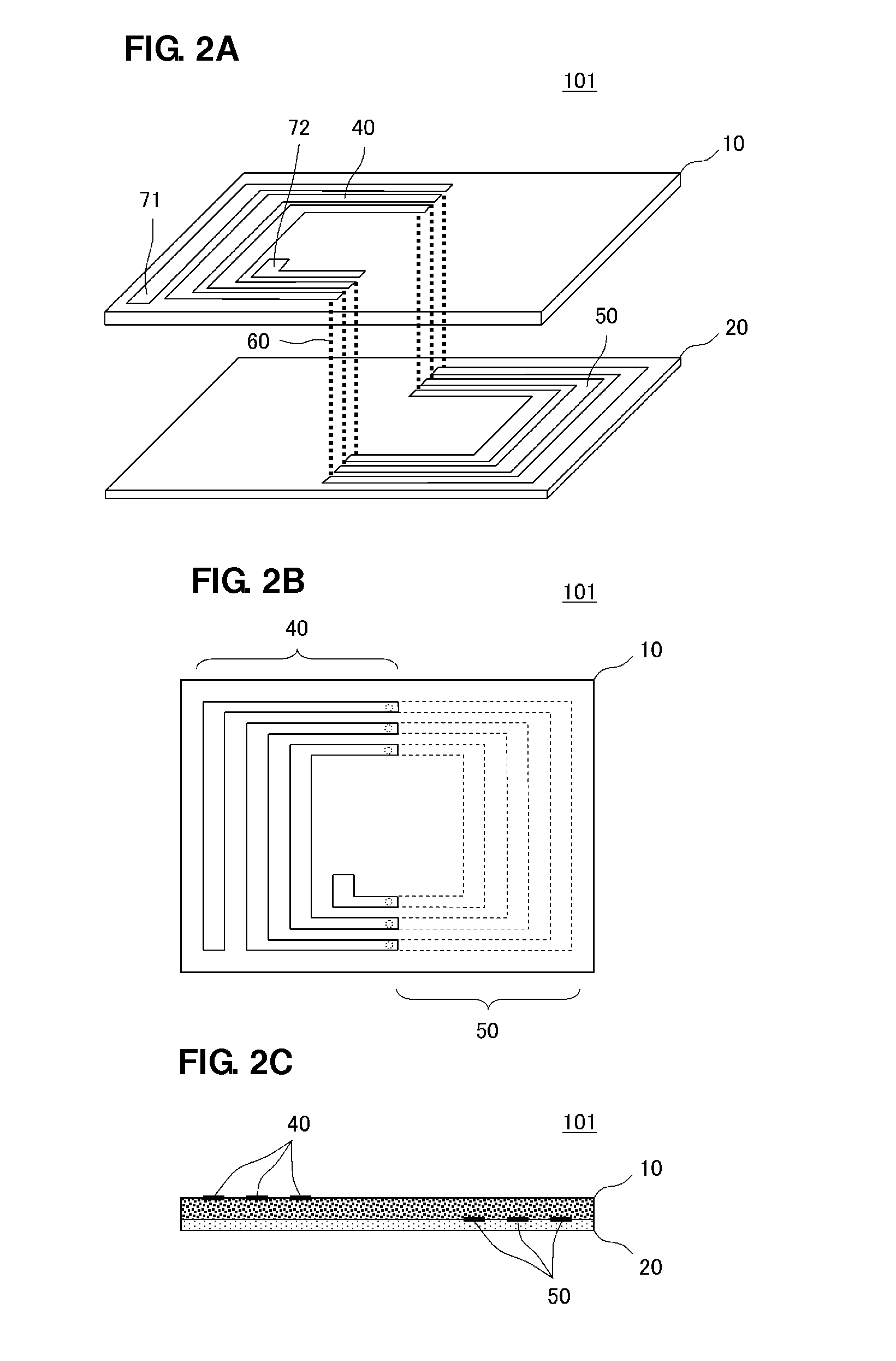
[0037]FIG. 2A is an exploded perspective view of an antenna device 101 according to a first preferred embodiment of the present invention. FIG. 2B is a plan view of the antenna device 101. FIG. 2C is a front view of the antenna device 101.

[0038]The antenna device 101 is configured as an antenna device preferably for use in transmitting and receiving high-frequency signals in a high frequency (HF) range, such as 13.56 MHz, for example. As described below, the antenna device 101 is arranged inside a terminal casing of a communication terminal apparatus, such as a cellular phone, for example.

[0039]As illustrated in FIGS. 2A-2C, the antenna device 101 includes an antenna coil. The antenna coil includes a first conductive pattern 40 disposed on a first major surface (upper surface in FIGS. 2A-2C) of a magnetic sheet 10, a second conductive pattern 50 disposed on a first major surface (upper surface in FIGS. 2A-2C) of a non-magnetic sheet 20, and an interlayer conductor (via electrode) 60...

second preferred embodiment

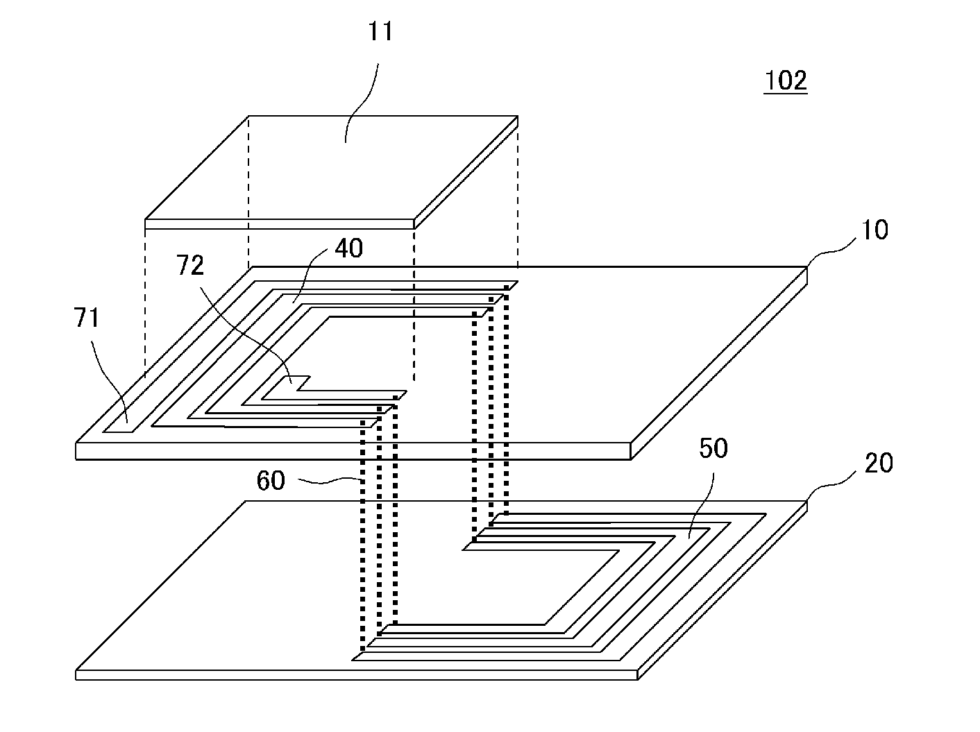
[0052]FIG. 4A is an exploded perspective view of an antenna device 102 according to a second preferred embodiment of the present invention. FIG. 4B is a front view of the antenna device 102. The antenna device 102 is the one in which the antenna device 101 illustrated in the first preferred embodiment further includes a magnetic sheet 11.

[0053]The added magnetic sheet 11 is stacked on the first conductive pattern 40 on the first major surface of the magnetic sheet 10 so as to cover a portion of the first conductive pattern 40. The input / output terminal 71, which is one end of the antenna coil, and the input / output terminal 72, which is another end thereof, are exposed.

[0054]FIG. 5 is a partial cross-sectional view that illustrates the configuration of a communication terminal apparatus 202 in which the antenna device 102 is incorporated. In FIG. 5, the front side, that is, the surface D with an input portion / display portion of the communication terminal apparatus 202 faces downward....

third preferred embodiment

[0057]FIG. 6A is an exploded perspective view of an antenna device 103 according to a third preferred embodiment of the present invention. FIG. 6B is a front view of the antenna device 103. The antenna device 103 includes a plurality of non-magnetic sheets. The first and second conductive patterns in the antenna device 103 are disposed on a plurality of layers. The first and second conductive patterns define a helical or substantially helical antenna coil.

[0058]A half-loop first conductive pattern 41 is disposed on the first major surface of the magnetic sheet 11. A half-loop first conductive pattern 42 and the input / output terminals 71 and 72 are disposed on a first major surface of a non-magnetic sheet 21. A half-loop second conductive pattern 51 is disposed on a first major surface of a non-magnetic sheet 22. A half-loop second conductive pattern 52 is disposed on a first major surface of a non-magnetic sheet 23. Interlayer conductors 61 and 64 are disposed in the non-magnetic sh...


PUM


Abstract

An antenna device includes an antenna coil including a first conductive pattern disposed on a first major surface of a magnetic sheet, a second conductive pattern disposed on a first major surface of a non-magnetic sheet, and an interlayer conductor connecting the first conductive pattern and second conductive pattern. The antenna coil including the first conductive pattern and second conductive pattern defines a spiral or substantially spiral pattern. The antenna device is a resin multilayer structure in which its base body is a laminate of the magnetic layer and non-magnetic layer and the predetermined patterns are disposed inside and outside the laminate.

Description

BACKGROUND OF THE INVENTION[0001]1. Field of the Invention[0002]The present invention relates to an antenna device preferably for use in an RFID system or short-range wireless communication system that communicates with partner equipment through an electromagnetic field signal.[0003]2. Description of the Related Art[0004]An antenna device for use in an HF-band communication system, such as Felica (registered trademark) or NFC, is disclosed in Japanese Unexamined Patent Application Publication No. 2002-325013. FIG. 1 is a front view that illustrates the structure of the antenna device described in Japanese Unexamined Patent Application Publication No. 2002-325013.[0005]An antenna coil 30 illustrated in FIG. 1 includes an air-core coil 32 including spirally wound conductors 31 (31a, 31b, 31e, 31d) in a plane on a film 32a and a flat-shaped magnetic core member 33 disposed in the air-core coil 32 so as to be positioned substantially in parallel with the plane of the air-core coil 32. T...

Claims


Application Information

Patent Timeline
Patent Type & Authority Applications(United States)
IPC IPC(8): H01Q7/06
CPCH01Q1/38H01Q7/06H01Q1/40H01Q1/243H01Q9/27H01L2224/16225H01L2924/19105H01L2924/19106
Inventor KATO, NOBORUSASAKI, JUNISHINO, SATOSHI
Owner MURATA MFG CO LTD
Why Eureka
Try Eureka