Hollow Fiber with Gradient Properties and Method of Making the Same

a gradient and fiber technology, applied in the field of hollow fibers with nanostructure reinforcement, can solve the problems of limiting the benefits of such higher-performance fibers, limiting the interface properties of carbon fibers with high moduli and strength, and known methods may not overcome the susceptibility to decreased interface properties between fibers and matrixes

Active Publication Date: 2013-06-13
THE BOEING CO
View PDF7 Cites 11 Cited by
  • Summary
  • Abstract
  • Description
  • Claims
  • Application Information

AI Technical Summary

Benefits of technology

[0011]This need for an improved fiber with more-tailorable properties for use in composite materials and a method of making the same is satisfied. As discussed in the below detailed description, embodiments of the improved fiber with more-tailorable properties and a method of making the same may provide significant advantages over known materials and methods.
[0016]In another embodiment of the disclosure there is provided a method of making a hollow fiber having improved resistance to microfracture formation at a fiber-matrix interface. The method comprises mixing in a first solvent a plurality of nanostructures, one or more first polymers, and a fugitive polymer which is dissociable from the nanostructures and the one or more first polymers, in order to form an inner-volume portion mixture. The method further comprises mixing in a second solvent one or more second polymers in order to form an outer-volume portion mixture. The method further comprises spinning the inner-volume portion mixture and the outer-volume portion mixture and extracting the fugitive polymer from the inner-volume portion mixture in order to form a precursor fiber. The method further comprises heating the precursor fiber to oxidize the precursor fiber and to change a molecular-bond structure of the precursor fiber. The method further comprises obtaining a hollow fiber. The hollow fiber comprises an inner-volume portion having a first-core portion with the nanostructures and with the one or more first polymers being oriented in a direction parallel to a longitudinal axis of the hollow fiber. The inner-volume portion further has one or more hollow second-core portions, the first-core portion being in contact with and encompassing the one or more hollow second-core portions. The hollow fiber further comprises an outer-volume portion having the one or more second polymers, the outer-volume portion being in contact with and completely encompassing the inner-volume portion. The inner-volume portion has at least one of a tensile modulus and a strength that are higher than at least one of a tensile modulus and a strength of the outer-volume portion, resulting in the hollow fiber having an improved resistance to microstructure formation at a fiber-matrix interface.

Problems solved by technology

Carbon fibers with high moduli and strengths may have issues at the fiber-matrix interface when there is a mismatch between the stiffness of the matrix and the fiber.
However, such known composite materials have shown a susceptibility to decreased interface properties between the fiber and matrix, thus limiting the benefits available from such higher-performance fibers.
However, such known methods may not overcome the susceptibility to decreased interface properties between the fiber and matrix while still providing improved fiber properties.
Moreover, such known methods may increase the weight of the composite materials and may increase costs of manufacturing and production of the composite materials.
However, such known composite materials may suspend the carbon nanotubes in resin resulting in random orientation of the nanotubes between adjacent fiber plies.
Moreover, the addition of even small amounts of carbon nanotubes to a liquid resin tends to dramatically increase its viscosity and, thus, decrease its processability.
Moreover, reduction in the overall weight of composite structures and parts may be desirable for aircraft, spacecraft, and other vehicles, as increased weight results in increased use of fuel, and in turn, increased costs.

Method used


Image

  • Hollow Fiber with Gradient Properties and Method of Making the Same
  • Hollow Fiber with Gradient Properties and Method of Making the Same
  • Hollow Fiber with Gradient Properties and Method of Making the Same

Examples


Embodiment Construction

[0033]Disclosed embodiments will now be described more fully hereinafter with reference to the accompanying drawings, in which some, but not all of the disclosed embodiments are shown. Indeed, several different embodiments may be provided and should not be construed as limited to the embodiments set forth herein. Rather, these embodiments are provided so that this disclosure will be thorough and complete and will fully convey the scope of the disclosure to those skilled in the art.

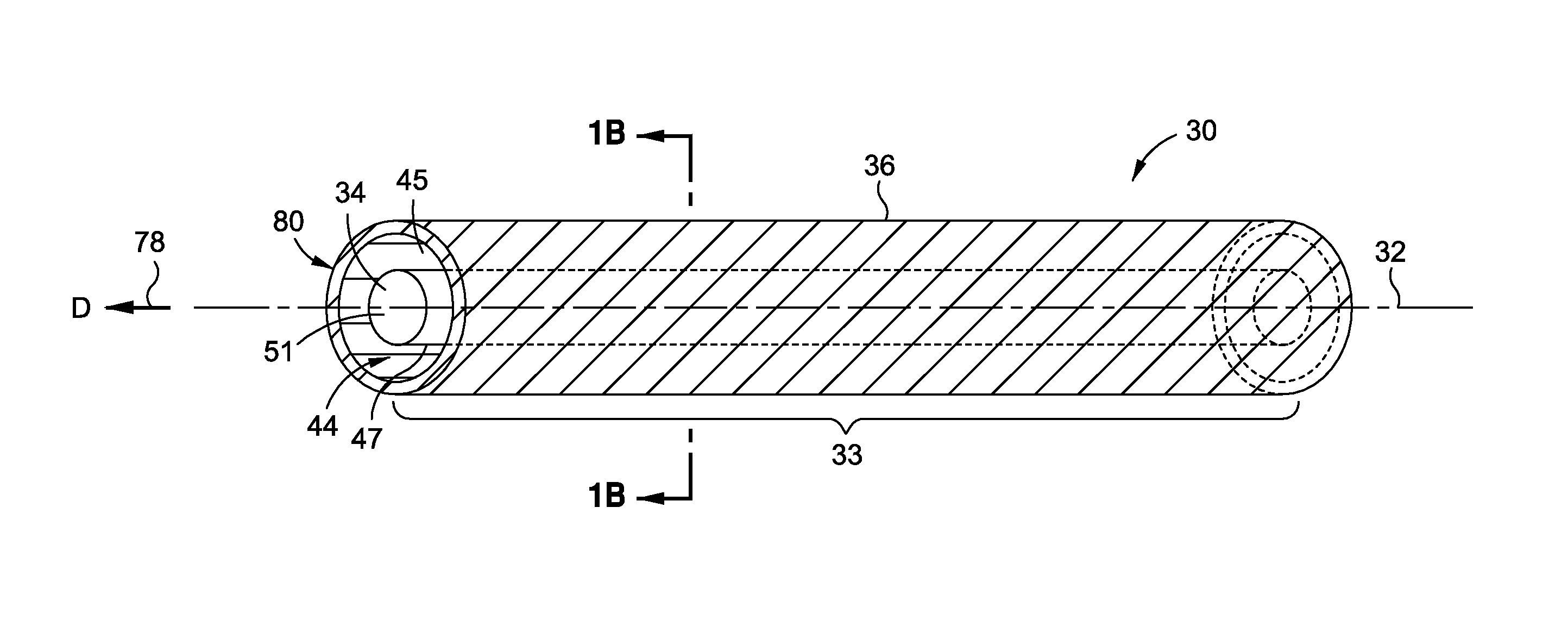
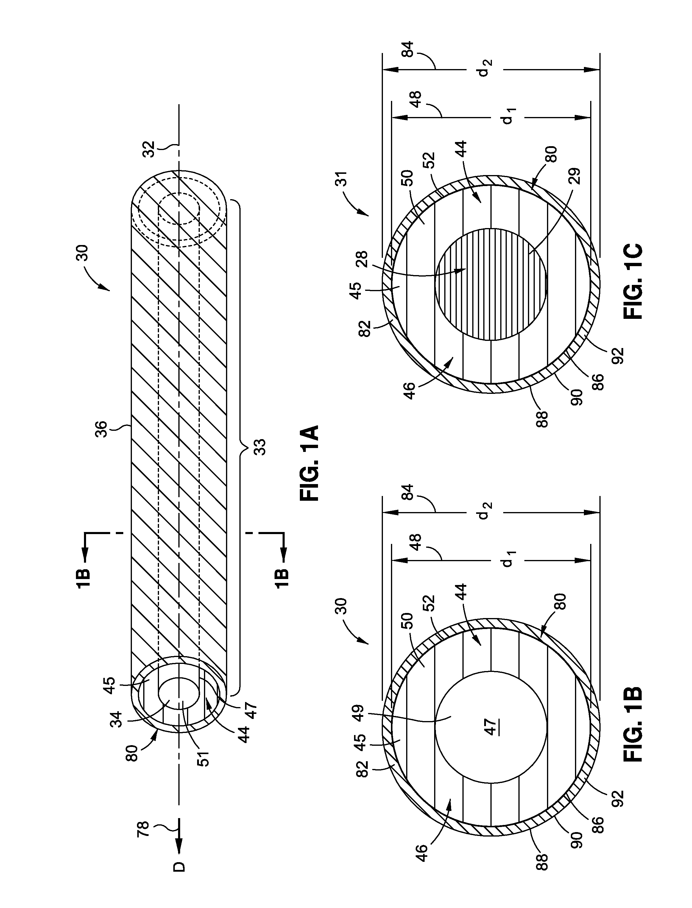
[0034]Now referring to the Figures, in an embodiment of the disclosure, as shown in FIGS. 1A-1C, there is provided a hollow fiber 30. FIG. 1A is an illustration of a perspective schematic view of one of the embodiments of the hollow fiber 30 of the disclosure. FIG. 1B is an illustration of a cross-section taken along lines 1B-1B of the hollow fiber 30 of FIG. 1A. FIG. 1C is an illustration of a cross-section of a precursor fiber 31 with a fugitive polymer core portion 28 prior to conversion to the hollow f...


PUM

PropertyMeasurementUnit
lengthaaaaaaaaaa
lengthaaaaaaaaaa
melting pointaaaaaaaaaa

Abstract

There is provided a hollow fiber and method of making. The hollow fiber has an inner-volume portion having a first-core portion and one or more hollow second-core portions. The first-core portion has nanostructures and one or more first polymers. The nanostructures act as an orientation template for orientation of the first polymers in a direction parallel to a longitudinal axis of the fiber. The first-core portion is in contact with and encompasses the hollow second-core portions. The hollow fiber further has an outer-volume portion having one or more second polymers. The outer-volume portion is in contact with and completely encompasses the inner-volume portion. The inner-volume portion has at least one of a tensile modulus and a strength that are higher than at least one of a tensile modulus and a strength of the outer-volume portion.

Description

BACKGROUND[0001]1) Field of the Disclosure[0002]The disclosure relates generally to hollow fibers with nanostructure reinforcement, and more particularly, to core-shell hollow carbon fibers with core nanostructure reinforcement and gradient properties for use in composite structures for aircraft and other structures.[0003]2) Description of Related Art[0004]Fiber-reinforced resin materials, or “composite” materials as they are commonly known, are used in a wide variety of structures and component parts, including in the manufacture of aircraft, spacecraft, rotorcraft, watercraft, automobiles, trucks, and other vehicles, because of high strength-to-weight ratios, corrosion resistance, and other favorable properties. In particular, in aircraft construction, composite structures and component parts are used in increasing quantities to form the fuselage, wings, tail section, skin panels, and other component parts of the aircraft.[0005]Conventional composite materials typically include gl...

Claims


Application Information

Patent Timeline
Patent Type & Authority Applications(United States)
IPC IPC(8): B32B27/04D02G3/00B29C47/00B29C48/05B29C48/09B29C48/18B29C48/21B82Y30/00
CPCD01D5/24D01D5/34Y10T428/2975D01F9/14D01F1/10Y10T428/24994B29C48/05B29C48/09B29C48/21B29C48/022D01D5/0038C01B32/00D01F9/155D01D5/003B29C48/18D01D5/0046B29L2031/731D01D5/06
Inventor TSOTSIS, THOMAS KARL
Owner THE BOEING CO
Why Eureka
Try Eureka