
Durable torsional vibration damper

a torsional vibration and damper technology, applied in the direction of shafts, engine lubrication, couplings, etc., can solve the problems of accelerating the wear of both frictional partners, abrasion of at least one of the frictional partners, and small attack angle of the intermediate flange relative to the input flange, etc., to achieve good radial bracing, prolong service life, and easy production

Inactive Publication Date: 2013-06-13
SCHAEFFLER TECH AG & CO KG
View PDF3 Cites 1 Cited by
  • Summary
  • Abstract
  • Description
  • Claims
  • Application Information

AI Technical Summary

Benefits of technology

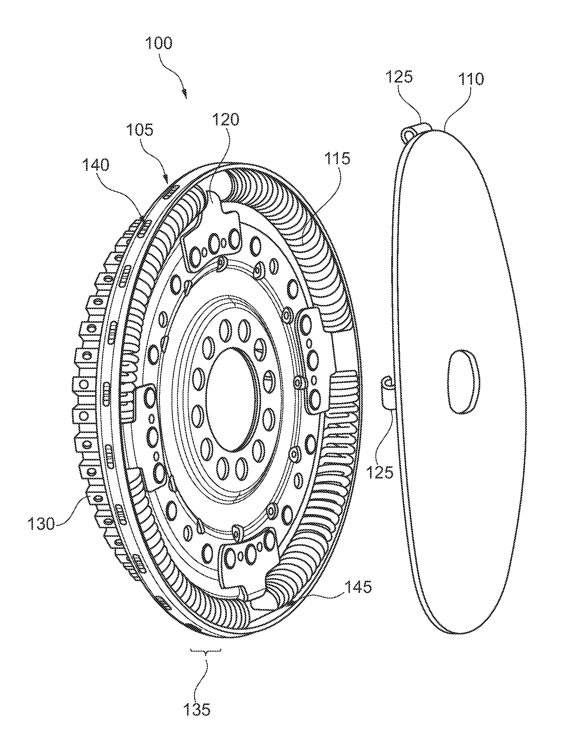
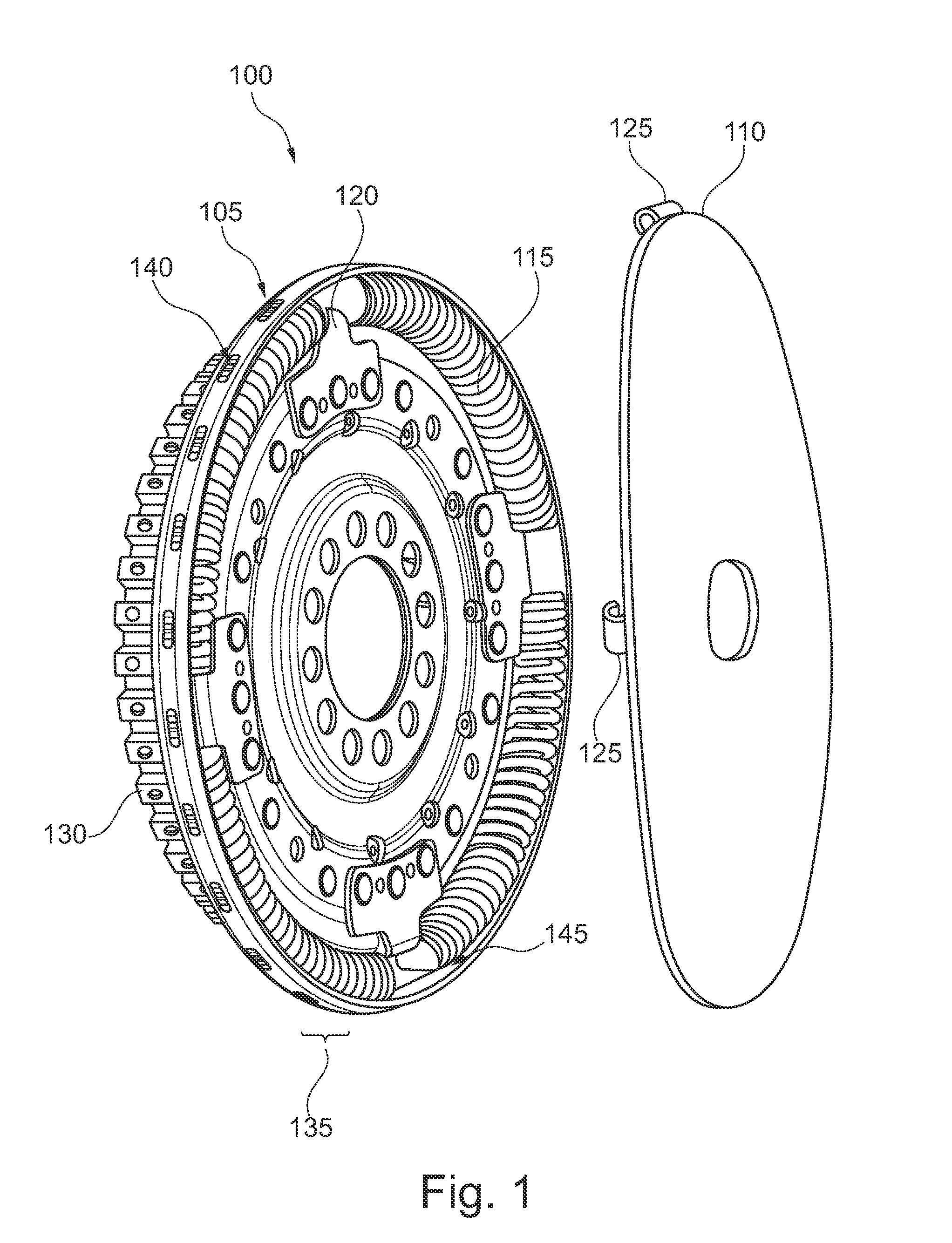
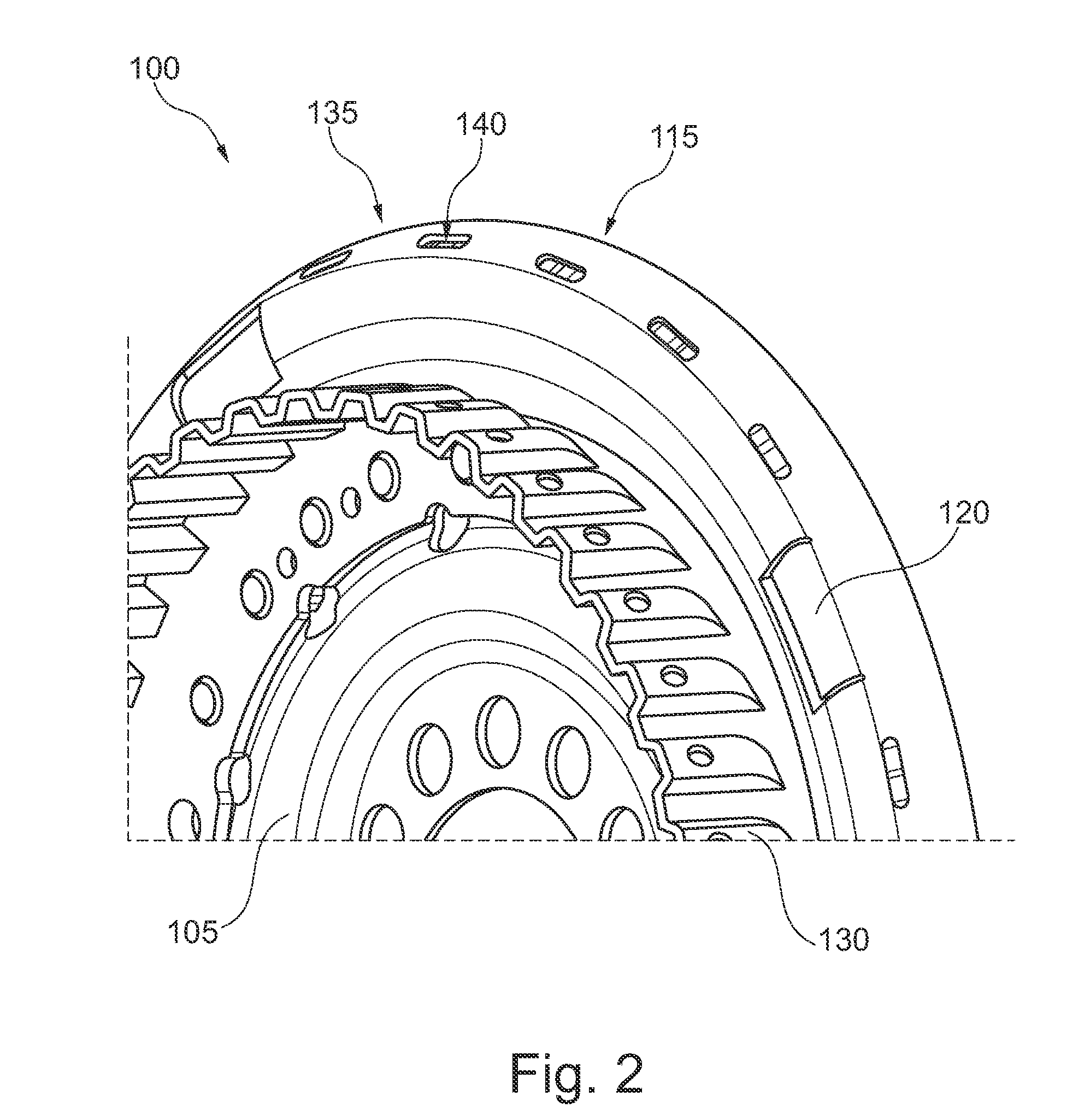
This patent text describes a way to prevent wear on a bow spring caused by friction with a holding device in a torsional vibration damper. The solution involves using oil to flush away abrasion particles caused by wear. An opening is created in the holding device to allow oil to flow through the area of contact, which reduces wear and tear and prolongs the life of the bow springs without the need for expensive measures. The opening is preferably located in a flat material of the flange and is formed by a lift flap that allows oil to flow through and initiate the flow of oil at the surface of the holding device without requiring an active supply of fresh oil.

Problems solved by technology

In particular, when used on a multi-cylinder reciprocating internal combustion engine, the torsional vibrations initiated by the internal combustion engine can result in deflections of the intermediate flange relative to the input flange with small angles of attack at a high frequency.
In the contact area between the flange and the bow spring there develops a rubbing of steel on steel, which causes an abrasion of at least one of the frictional partners.
That causes the abrasion particles to be further tumbled during the continuing operation of the torsional vibration damper and to be ground between the retainer and the bow spring, which further accelerates the wearing of both frictional partners.

Method used


Image

  • Durable torsional vibration damper
  • Durable torsional vibration damper
  • Durable torsional vibration damper

Examples


Embodiment Construction

[0025]At the outset, it should be appreciated that like drawing numbers on different drawing views identify identical, or functionally similar, structural elements of the invention. While the present invention is described with respect to what is presently considered to be the preferred aspects, it is to be understood that the invention as claimed is not limited to the disclosed aspect. The present invention is intended to include various modifications and equivalent arrangements within the spirit and scope of the appended claims.

[0026]Furthermore, it is understood that this invention is not limited to the particular methodology, materials and modifications described and as such may, of course, vary. It is also understood that the terminology used herein is for the purpose of describing particular aspects only, and is not intended to limit the scope of the present invention, which is limited only by the appended claims.

[0027]Unless defined otherwise, all technical and scientific ter...


PUM


Abstract

A torsional vibration damper for operation in an oil bath comprising an input flange for connecting to a drive motor, an output flange for connecting to a transmission, and a bow spring for the torsionally elastic coupling of the input flange to the output flange, where the bow spring is in contact radially on the outside with an encircling holding device that is formed on one of the flanges. At the same time, the holding device has an opening in the area of the bow spring, in order to enable a flow of oil through an area of contact of the bow spring with the holding device.

Description

CROSS-REFERENCE TO RELATED APPLICATIONS[0001]This application claims priority from German Patent Application No. 10 2011 087 865.3, filed on Dec. 7, 2011, which application is incorporated herein by reference.[0002]1. Field of the Invention[0003]The invention relates generally to torsional vibration dampers, more specifically to torsional vibration dampers operating in an oil bath, and, even more specifically, to torsional vibration dampers operating in an oil bath in a drivetrain of a motor vehicle.[0004]2. Background of the Invention[0005]A known serial torsional vibration damper comprises an input flange, an intermediate flange and an output flange, wherein a bow spring positioned radially outside is provided for the elastic transmission of torque from the input flange to the intermediate flange, and a compression spring positioned radially inside is provided for the elastic transmission of torque from the intermediate flange to the output flange. The input flange is usually shap...

Claims


Application Information

Patent Timeline
Patent Type & Authority Applications(United States)
IPC IPC(8): F16D3/12
CPCF16D3/12F16F15/16F16F15/123
Inventor WERNER, MARKUS
Owner SCHAEFFLER TECH AG & CO KG
Learn More