Electrical Submersible Pump Monitoring and Failure Prediction

a technology of submersible pumps and failure prediction, which is applied in the direction of seismology, water-logging instruments, and using reradiation. it can solve the problems of recurrent problems, failure of downhole esp components, and gradual decrease of pump efficiency

Active Publication Date: 2013-06-13
SAUDI ARABIAN OIL CO
View PDF19 Cites 28 Cited by
  • Summary
  • Abstract
  • Description
  • Claims
  • Application Information

AI Technical Summary

Benefits of technology

[0011]Briefly, the present invention provides a new and improved apparatus for monitoring performance of an electrical submersible pump in a well based on analysis of pump electrical current. The apparatus according to the present invention includes an analyzer of the frequency spectrum of the energy in the pump electrical current, and a wavelet analyzer of the waveform of the pump electrical current identifying time variations of the pump electrical current. The apparatus also includes an analyzer of the pump electrical current to identify dynamic behavior of the pump during pumping, and a phase space analyzer forming a measure of the identified dynamic behavior of the pump based on fluctuations in the pump electrical current. A graphical interface of the apparatus forms indications from the analyzers for monitoring performance of the pump to detect disturbances in performance of the pump.
[0012]The present invention also provides a new and improved method of monitoring performance of an electrical submersible pump in a well based on analysis of pump electrical current. The frequency spectrum of the energy in the pump electrical current is analyzed, and the waveform of the pump electrical current is analyzed to identify time variations of the pump electrical current. The pump electrical current is analyzed to identify dynamic behavior of the pump during pumping, and a measure of the identified dynamic behavior of the pump is formed based on fluctuations in the pump electrical current. Indications of the results of the analysis are formed for monitoring performance of the pump to detect disturbances in performance of the pump.

Problems solved by technology

During production from the formation, mineral deposits from the formation fluid occurred in and around the ESP's, well tubing and other subsurface equipment, and have caused recurrent problems.
One of the common failure reasons in ESP assemblies resulted from scale build-up in the pump stages, where scale gradually formed around the impeller vanes and eventually blocked fluid flow.
Scale deposits led to a gradual decrease of the pump efficiency until pump failure eventually occurred.
Problems with scale and other subsurface conditions as well as extended service eventually led to failure of the downhole ESP components, usually the pump.
As noted, however, this form of failure analysis could only be performed after the failure occurred, and after the downhole or subsurface ESP components had been extracted from the well.
Both the ESP failure and its removal from the well caused production from the well to be stopped.

Method used


Image

  • Electrical Submersible Pump Monitoring and Failure Prediction
  • Electrical Submersible Pump Monitoring and Failure Prediction
  • Electrical Submersible Pump Monitoring and Failure Prediction

Examples


Embodiment Construction

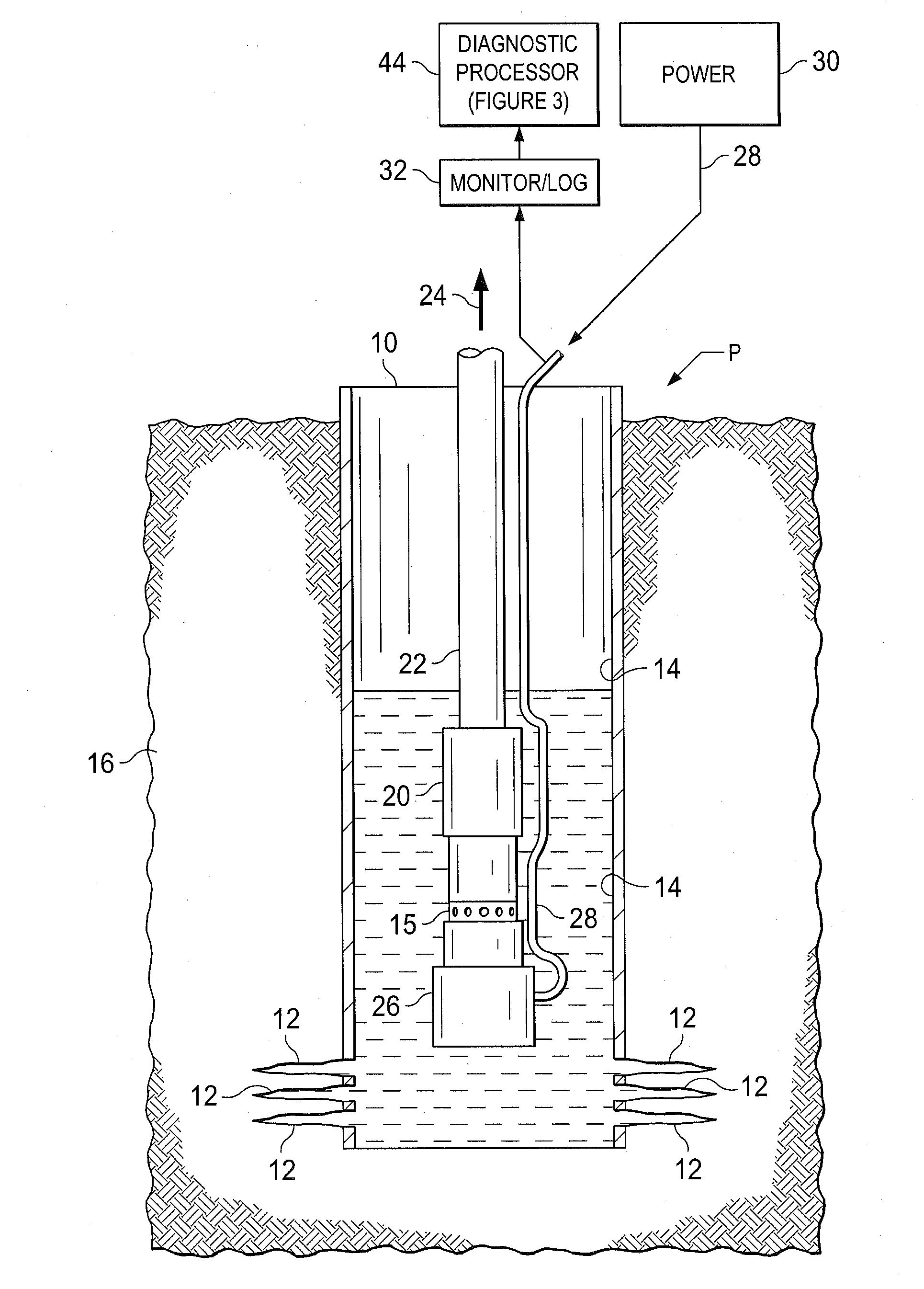
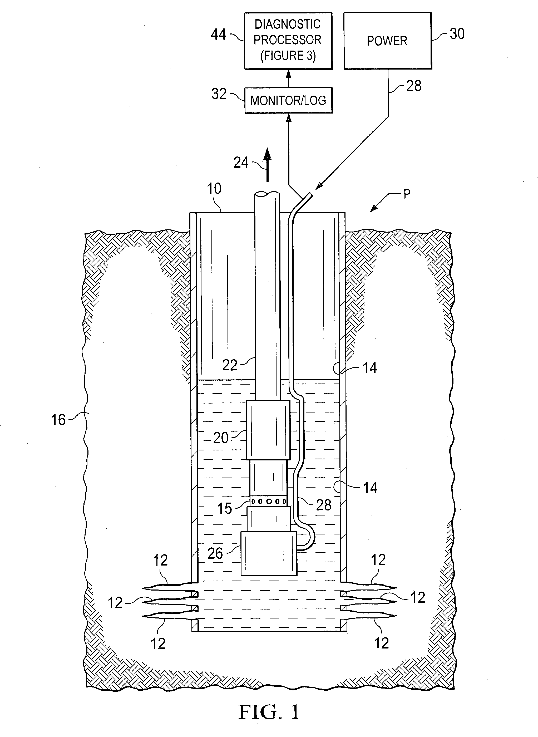
[0019]Referring to FIG. 1, an electrical submersible pump assembly P is shown in a well 10 at the location of a number of perforations 12 formed in a casing 14 to allow entry through an inlet or intake section 15 of oil and other hydrocarbon fluids from a formation 16 in a subsurface reservoir. The casing 14 may also be a liner installed within larger diameter casing in the well 10. A pump section 20 of the electrical submersible pump assembly P is immersed in the fluids in the casing 14. The electrical submersible pump assembly P is suspended within the casing 14 on tubing 22 at the well depth of the perforations 12 so that the pump section 20 may drive or pump fluids in the casing 14 as indicated at 24 to a collection facility at the surface.

[0020]The pump section 20 includes a suitable number of centrifugal pump stages which are driven by an alternating current pump motor 26. The pump motor 26 receives operating electrical power over a cable 28 from a suitable power source 30 at ...


PUM


Abstract

Current supplied to electrical submersible pumps in wells is monitored, and signal processing based on wavelet analysis and phase diagram analysis is performed on the data obtained from monitoring. An incipient malfunction of the electrical submersible pump, such as one due to scale build-up in and around the pump, can be detected at an early stage.

Description

CROSS REFERENCE TO RELATED APPLICATIONS[0001]This application claims priority from U.S. Provisional Application No. 61,570,030, filed Dec. 13, 2011. For purposes of United States patent practice, this application incorporates the contents of the Provisional Application by reference in entirety.BACKGROUND OF THE INVENTION[0002]1. Field of the Invention[0003]The present invention relates to monitoring performance and to failure prediction of electrical submersible pumps in wells.[0004]2. Description of the Related Art[0005]Submersible pumps have been used in wells for oil production at various depths and flow rates. The pumps are typically electrically powered and referred to as Electrical Submersible Pumps (ESP's). ESP's were one of several forms of what is known as artificial lift. ESP's were located in tubing in the well and provided a relatively efficient form of production.[0006]An ESP system used in oil production included surface components at the production wellhead or platfor...

Claims


Application Information

Patent Timeline
Patent Type & Authority Applications(United States)
IPC IPC(8): G01V3/06G01V3/38
CPCG01V3/06H02P31/00E21B47/0007G01V3/38E21B47/008
Inventor NOUI-MEHIDI, MOHAMED NABILBUKHAMSEEN, AHMED YASIN
Owner SAUDI ARABIAN OIL CO
Why Eureka
Try Eureka