Multi-ecu simiulation by using 2-layer peripherals with look-ahead time

a look-ahead time and peripheral technology, applied in the field of simulation systems implemented by computers, can solve problems such as inability to use product verification applications, complex software of ecus, and failure to achieve reproducibility of operations,

Inactive Publication Date: 2013-06-13
IBM CORP
View PDF7 Cites 22 Cited by
  • Summary
  • Abstract
  • Description
  • Claims
  • Application Information

AI Technical Summary

Problems solved by technology

With an integrated vehicle position stabilizing device (ESC: Electronic stability control) for preventing lateral slipping or the like of the vehicle, coordination with the braking device such as the brakes or the like is essential, and thus ECU software is complex.
However, the operation differs from the software that is actually included in the ECU, so use for product verification applications is not possible.
On the other hand, V-HILS uses completed ECU software, and is extremely promising as a method for resolving unanticipated actions (bugs) that are discovered in the software, but there are no examples where an operation with reproducibility has been achieved.
HILS is always performed in order to confirm the final behavior of the completed ECU board, but reproducibility is not insured even if a failure is discovered and therefore cannot be used for the purpose of debugging.
Therefore, even if the actual vehicle is prototyped, reproducibility of the operation cannot be expected.
This is the same reason that debugging a parallel distributed system is extremely difficult.
With this type of HILS configuration, or in other words with a configuration where the ECU board at the plant simulator are loosely linked, operation consistency cannot be achieved even if each of the components are sped up.
This increases the speed of the plant simulator, but decreases the speed of the processor emulator.
There is also a problem with overhead in addition to the problem with data error.
An approach where the synchronous interval is fixed and reduced to the maximum limit cannot be a method for practically resolving both aspects of data error and overhead.
(1) Time synchronization: With this method, the processor emulator executes the simulation while mutually communicating. There is a trade-off between execution speed and time precision, and there are quantization errors for time. Furthe

Method used


Image

  • Multi-ecu simiulation by using 2-layer peripherals with look-ahead time
  • Multi-ecu simiulation by using 2-layer peripherals with look-ahead time
  • Multi-ecu simiulation by using 2-layer peripherals with look-ahead time

Examples


Embodiment Construction

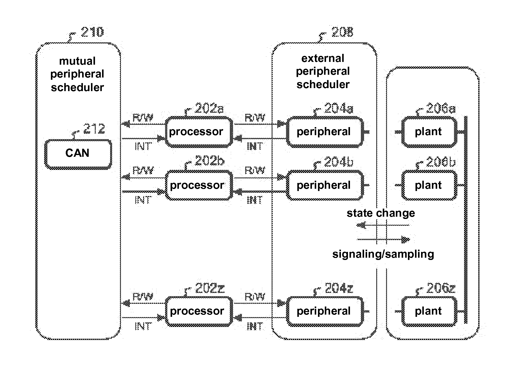
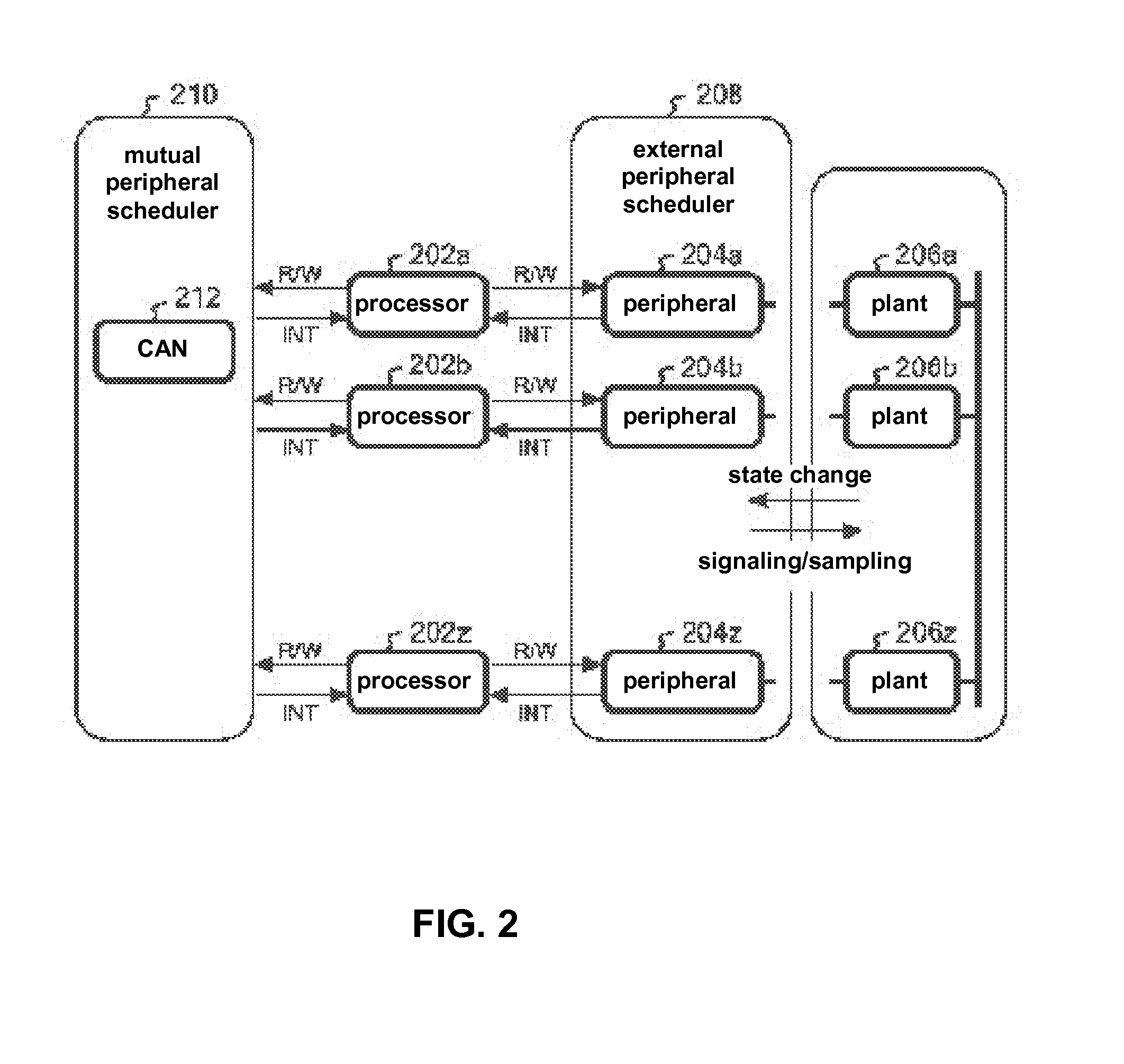
[0056]It is an object of the present invention to provide a technique that can execute a fast simulation with sufficient time precision and minimal data error for a system with a plurality of ECU and plants that mutually provide notification (interrupt) of asynchronous data. Notification of asynchronous data refers to notifying a controller of a regular state change of a plant, or asynchronous CAN communication between processors.

[0057]It is another object of the present invention to link three types of processor emulators, peripheral emulators, and plant simulators in order to simulate an entire system with an ECU and a plant subject to control thereof.

[0058]With the present invention, the peripherals are divided into three types, namely mutual peripherals, external peripherals, and internal peripherals, and a scheduler unique to each is provided. These three types of schedulers cooperate and efficiently achieve accurate linked operations.

[0059]The mutual peripherals are an interme...


PUM


Abstract

A method and system where a plurality of ECU is rapidly executed while avoiding deadlock by performing conservative event synchronization. The simulation system is provided with 4 layers, namely a processor emulator which is an ECU emulator, a plant simulator, a external peripheral scheduler, and a mutual peripheral scheduler. The external peripheral scheduler performs advanced execution of the plant simulator only during processor emulator reaction delay time (or the time until the next event). The notification to perform advanced execution of the processor emulator is provided until the actual plant simulator stop time. The mutual peripheral scheduler provides notification to the processor emulator to perform advanced execution only during communication delay timing between processor emulators (or the time until the next event). The processor emulator conservatively processes until the earliest time of the notification times. Each peripheral proceeds with processing until the earliest time of the accepted events.

Description

CROSS-REFERENCE TO RELATED APPLICATION[0001]This application is a National Phase Application based on PCT / JP2011 / 067132 which claims priority from Japanese Patent Application No. 2010-184845 filed Aug. 20, 2010, the entire contents of both of which are incorporated herein by referenceBACKGROUND OF THE INVENTION[0002]1. Field of the Invention[0003]The present invention relates to simulation of a physical system such as an automobile, and more specifically relates to a computer implemented simulation system.[0004]2. Description of Related Art[0005]Early in the 20th century, the automobile was made of mechanical components including engine for power, accelerator, steering wheel, transmission, and suspension, but almost know electrical devices were used other than the engine spark plugs and the headlights.[0006]However, since the 1970s, there has been a need to control engine efficiency as a result of air pollution and oil crises, and therefore at ECU is used for controlling the engine....

Claims


Application Information

Patent Timeline
IPC IPC(8): G06F17/50
CPCG05B17/02G06F17/5009G06F11/261G06F9/46G06F11/28G06F30/20
Inventor MATSUMURA, IKUOSHIMIZU, SHUICHI
Owner IBM CORP
Why Eureka
Try Eureka