
A combustor applied in thermophotovoltaic system

a thermophotovoltaic system and combustor technology, applied in the field of combustor, can solve the problems of insufficient flame stabilization of correlated heat recirculation, little room for fuel and air to be mixed, and low structure of structure, so as to achieve easy processing, reduce co and nox emissions, and enhance energy density

Active Publication Date: 2013-06-20
NAT CHENG KUNG UNIV
View PDF5 Cites 10 Cited by
  • Summary
  • Abstract
  • Description
  • Claims
  • Application Information

AI Technical Summary

Benefits of technology

The invention provides a combustor for a thermophotovoltaic system that improves the energy efficiency of the emitter and photovoltaic cell plate. The combustor is made of metal-oxide-deposited quartz, which increases energy density and allows for easy processing. The reversed tube redirects the flow of hot product gas generated during combustion, reheating the outer wall of the combustor and creating a swirling flame that provides uniform illumination and reduces emissions of CO and NOx.

Problems solved by technology

However, when the combustor is physically shrunk to a critical size (less than 1 cm), the structure thereof provides little room for the fuel and the air to be mixed.
As a result, the fuel and the air are mixed imperfectly, and the correlated heat recirculation is insufficient for the flame stabilization.
Hence, thermal dispersion augments and the emitter adversely offers inadequate light energy for the conversion into electricity through the photovoltaic cell plate.
Nonetheless, the radiant spectrum of the silicon carbide is directed to a broad spectrum, meaning that when the surface temperature of the silicon carbide reaches about 1000 K, most energy is distributed out of the spectrum scope that the photovoltaic cell plate is capable of converting, which is thus wasteful.
Further, photons that are not absorbed unfavorably fall on the ultrared section, so the photovoltaic cell plate is accordingly heated up since more thermal radiation is absorbed, which readily results in failure of the photovoltaic cell plate due to the overheating temperature.

Method used


Image

  • A combustor applied in thermophotovoltaic system
  • A combustor applied in thermophotovoltaic system
  • A combustor applied in thermophotovoltaic system

Examples


Embodiment Construction

[0020]Wherever possible, the same reference numbers are used in the drawings and the description to refer to the same or like parts.

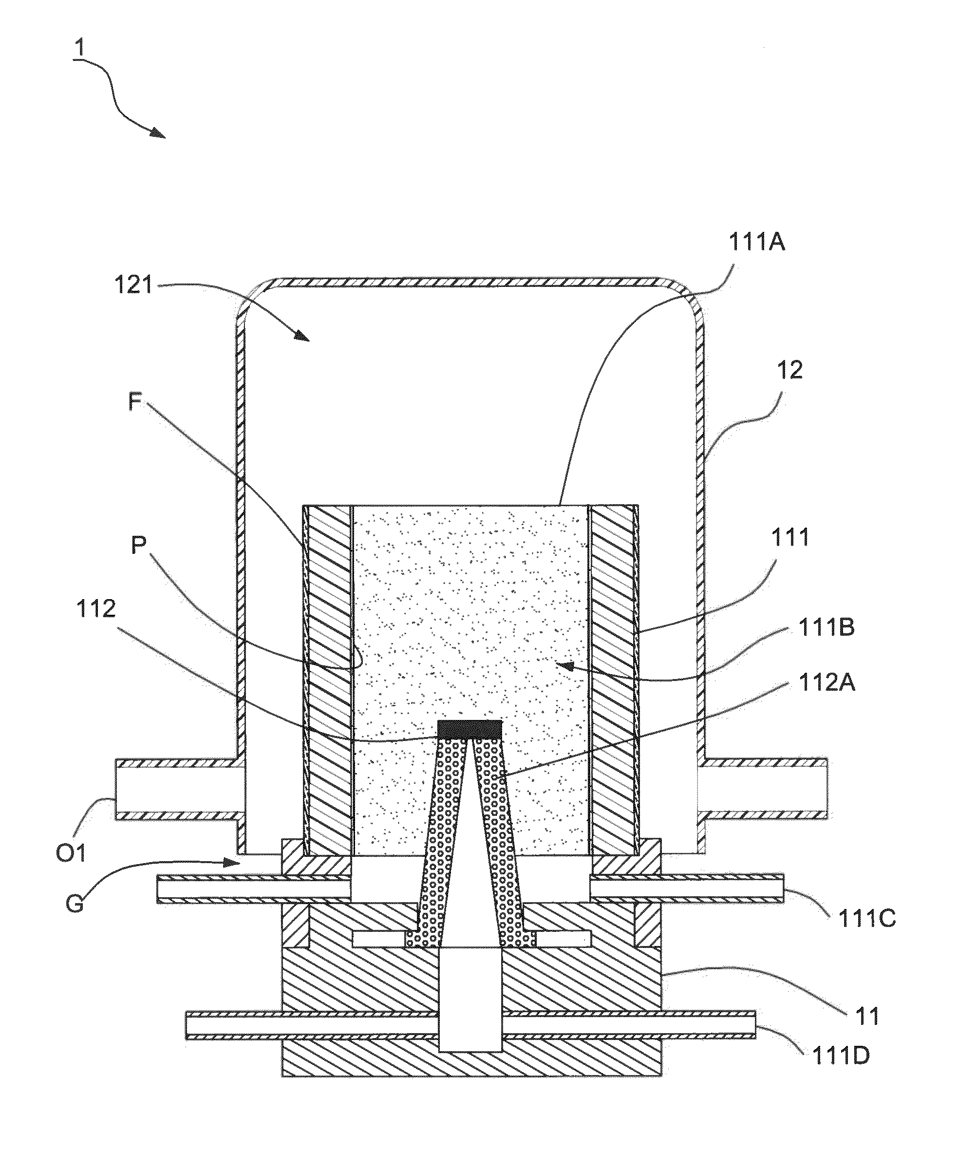
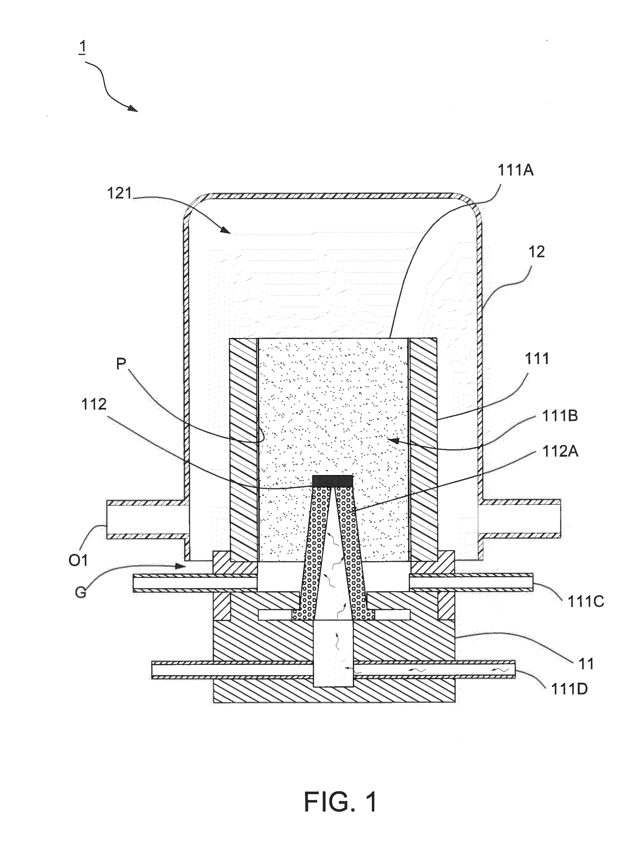
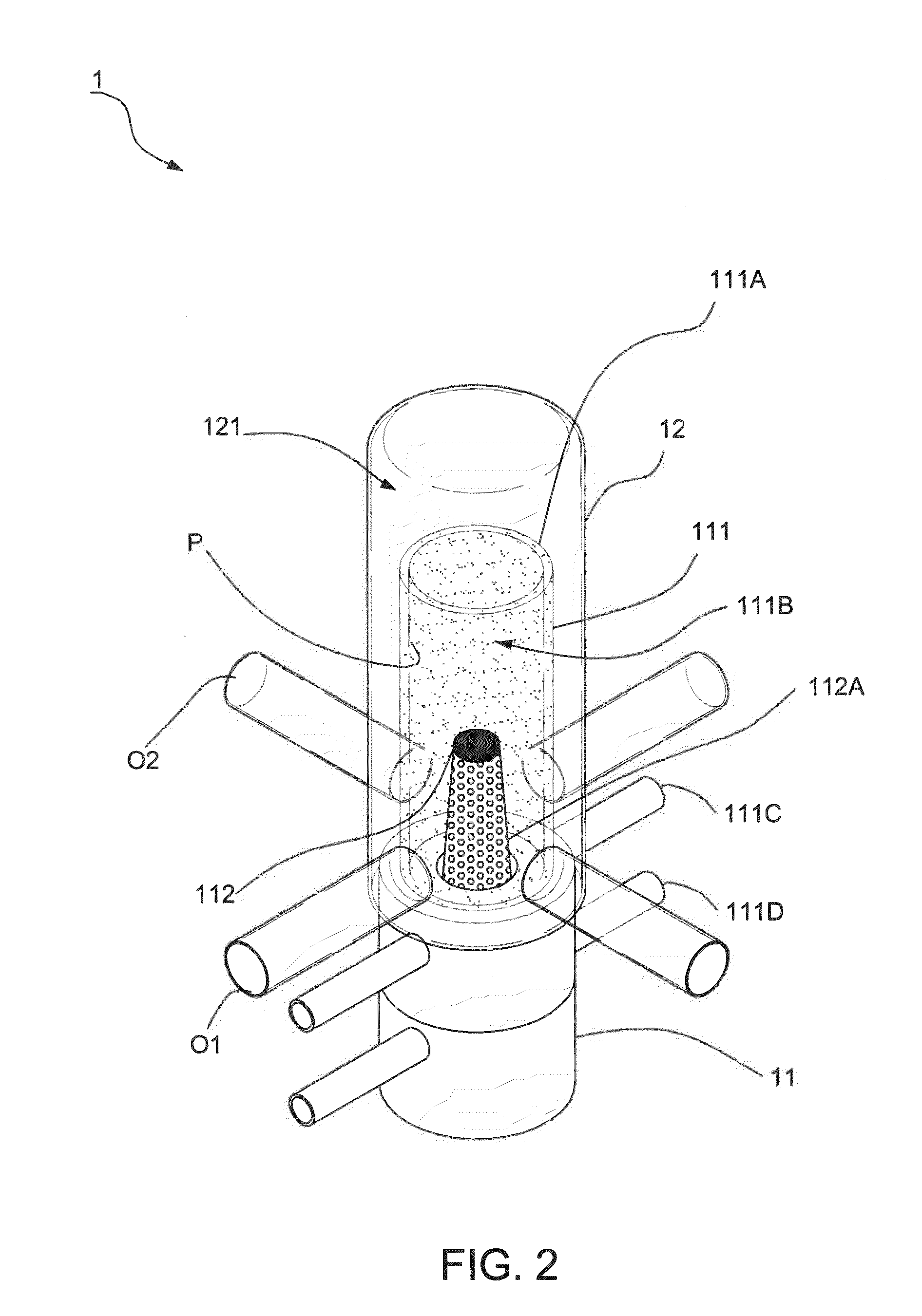
[0021]Referring to FIGS. 1 to 3, a first preferred embodiment of the present invention is shown. A combustor 1 applied in thermophotovoltaic system comprises a combustion device 11 and a reversed tube 12. Wherein, the combustion device 11 includes a combustion body 111 and a burning unit 112 disposed in the combustion body 111. The combustion body 111 is transparent and heat-resistant. The combustion body 111 includes an inner wall, an outer wall, an opening 111A surrounded by an end of the inner wall, and an accommodating room 111B cooperatively formed by a surrounding of the inner wall as well as communicated with the opening 111A. The burning unit 112 is disposed to insert into the accommodating room 111B. A burning-supported medium P is attached to the inner wall of the combustion body 111. In this embodiment, the burning-supported medium P adopts m...


PUM


Abstract

A combustor applied in thermophotovoltaic system comprises a combustion device and a reversed tube covering the combustion device. The combustion device includes a combustion body made of a transparent, and temperature resistant material and a burning unit disposed in the combustion body. When a burning-supported medium is adopted during burning via the burning unit, the radiant intensity is increased. The reversed tube thence further redirects the hot product gas for reheating an outer wail of the combustion body in combustion. Therefore, uniform illumination is accordingly resulted for enhancing the radiant intensity. Accordingly, a photovoltaic cell plate connected to the combustor preferably transforms light into electricity. The present invention fully utilizes a micro system as well as miniature energy to offer advanced electricity.

Description

BACKGROUND OF THE INVENTION[0001]1. Field of the Invention[0002]The present invention relates to a combustor, particularly to a combustor applied in thermophotovoltaic system.[0003]2. Description of the Related Art[0004]Various electronic products are vigorously developed today, and so are the correlated markets, such as the related power system (battery). Herein, in order to conquer problems that the traditional batteries merely provide limited ability of storing energy, various studies of enhancing energy in a micro device are contributed. For example, electronic products or power supply systems that have to be continuously operated or that consume high power could be readily portable and able to persistently work by means of the micro combustors applied in the thermophotovoltaic power system (TPV).[0005]Generally, the thermophotovoltaic system mainly comprises three elements: the heat source, the emitter, and the PV cell array. The heat source is provided for heating the emitter,...

Claims


Application Information

Patent Timeline
Patent Type & Authority Applications(United States)
IPC IPC(8): F23D11/00
CPCF23M5/00F23M9/06F23C3/00F23D5/04F23D5/123H02S10/30F23C2900/03001F23C2900/03006F23M2900/05004F23M2900/13004F23D17/002Y02E10/50
Inventor LI, YUEH-HENGCHEN, GUAN-BANGCHAO, YEI-CHINCHENG, TSARNG-SHENGLI, HONG-YUAN
Owner NAT CHENG KUNG UNIV
Learn More