Photoacoustic wave measuring apparatus

a technology of photoacoustic waves and measuring apparatus, which is applied in the direction of instruments, specific gravity measurement, applications, etc., can solve the problems of reducing the light efficiency in the deep portions of living organisms, and not being suitable for objects, and achieve the effect of reducing the effect of an interface signal

Inactive Publication Date: 2013-06-27
CANON KK
View PDF5 Cites 7 Cited by
  • Summary
  • Abstract
  • Description
  • Claims
  • Application Information

AI Technical Summary

Benefits of technology

[0026]According to the present invention, it is possible to provide technology for performing suitable image construction at various depths inside an object while reducing the effects of an interface signal, when performing photoacoustic wave measurement.
[0027]Further features of the present invention will become apparent from the following description of exemplary embodiments with reference to the attached drawings.

Problems solved by technology

However, since the interface region between the ultrasound wave probe and the living organism is not illuminated directly, then the use efficiency of the light in the deep portions of the living organism is diminished.
Therefore, the method described in Patent Literature 1 has a problem in that it is not suitable for objects which require observation in a broad range, up to an including deep portions of the object, such as a breast.

Method used


Image

  • Photoacoustic wave measuring apparatus
  • Photoacoustic wave measuring apparatus
  • Photoacoustic wave measuring apparatus

Examples


Embodiment Construction

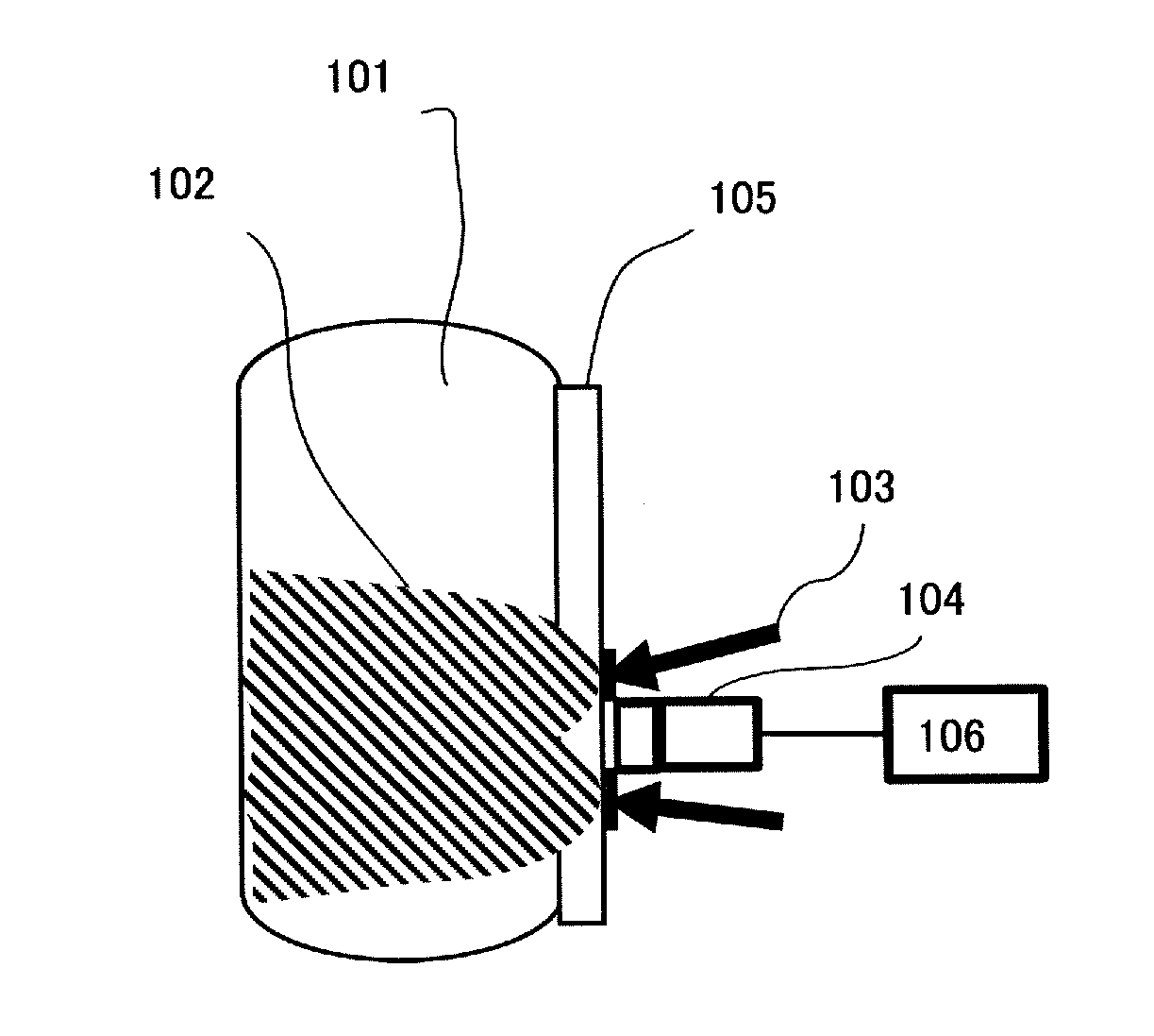
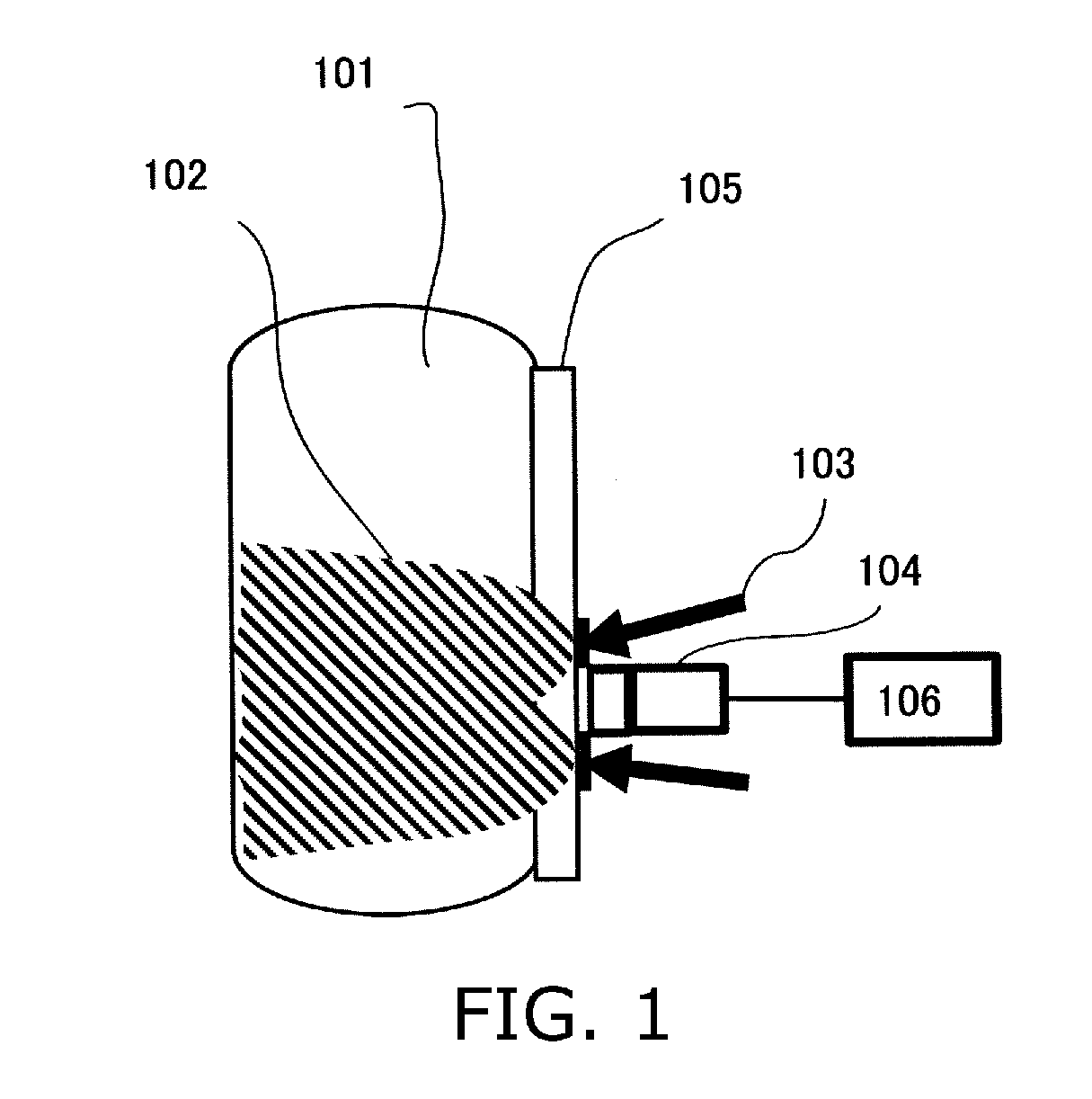
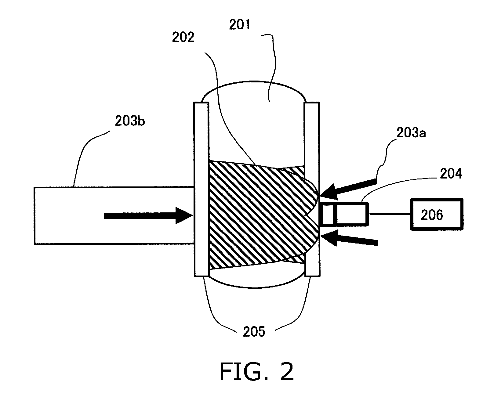
[0035]A concrete embodiment of the present invention is described below. In the present embodiment, a photo-acoustic mammography (PAM) apparatus which secures and diagnoses a breast is given as an example of a photoacoustic wave measuring apparatus. Object information refers to information reflecting variation in the acoustic impedance of the internal tissue of the object, the distribution of acoustic wave generating sources, the distribution of the initial sound pressure inside the object, or the distribution of the light energy absorption density which is derived from the initial sound pressure distribution, the absorption coefficient distribution, and the density distribution of the material which constitutes the tissue. The material density distribution is, for example, the oxygen saturation distribution, the oxidized or reduced hemoglobin density distribution, and the like. In the photoacoustic wave measuring apparatus, the object information data may be numerical data of vario...


PUM

PropertyMeasurementUnit
photoacoustic wave measuring apparatusaaaaaaaaaa
photoacoustic wave measuringaaaaaaaaaa
central frequencyaaaaaaaaaa

Abstract

A photoacoustic wave measuring apparatus, having: a probe including a plurality of devices which detect an acoustic wave generated by irradiating light onto an object; and a signal processor which acquires information about the object on the basis of an acoustic wave received by the devices, wherein the light is irradiated onto the object from the probe side; the probe includes: bright-field devices having a view angle covering a bright-field illumination area, which is an area where the light is irradiated, on the probe-side surface of the object; and dark-field devices having a field of view which does not cover the bright-field illumination area; and the signal processor uses an acoustic wave received by the dark-field devices when acquiring information about the object on the basis of a acoustic wave received before a predetermined time period is elapsed since the irradiation of light onto the object.

Description

TECHNICAL FIELD[0001]The present invention relates to a photoacoustic wave measuring apparatus which acquires information about, and creates an image of a living organism.BACKGROUND ART[0002]Recently, photo-acoustic tomography has been proposed which determines the distribution of an optical characteristics value in a living organism, with good accuracy, by using the characteristics of an acoustic wave (typically, an ultrasound wave) that produces little scattering inside a living organism compared to light (see Non Patent Literature 1). In the present specification, photo-acoustic tomography is referred to as “PAT”.[0003]When pulse light generated by a light source is irradiated onto a living organism, the pulse light propagates while diffusing in the living organism. An absorbing body contained in the living tissue absorbs energy of the propagated pulse light and generates an acoustic wave. By analyzing this acoustic wave signal, it is possible to obtain an optical characteristics...

Claims


Application Information

Patent Timeline
Patent Type & Authority Applications(United States)
IPC IPC(8): G01N21/17
CPCA61B5/0064A61B5/0091G01N29/2418A61B5/4312G01N21/1702A61B5/0095
Inventor ICHIHARA, SHIGERUKOBAYASHI, SHUICHI
Owner CANON KK
Why Eureka
Try Eureka