Rigid-flex circuit board and manufacturing method

a manufacturing method and circuit board technology, applied in the direction of circuit bendability/stretchability, contact member manufacturing, printed circuit aspects, etc., can solve the problems of affecting production yield, etching process produces large amount of toxic waste which is costly to handle, and the structure and fabricating method of existing rigid-flex circuit boards are affected. , to achieve the effect of reducing the complexity of the configuration and fabrication process, reducing the curing temperature, and high mechanical stability

Inactive Publication Date: 2013-06-27
DIGIPAS TECH INC
View PDF5 Cites 73 Cited by
  • Summary
  • Abstract
  • Description
  • Claims
  • Application Information

AI Technical Summary

Benefits of technology

[0008]A cost effective rigid-flex circuit board and its manufacturing method are disclosed with reduced complexity in its configuration and fabrication process. In accordance with the invention, the construction of the rigid-flex circuit board comprises the followings: (a) a flexible wiring interconnect section consist of an improved flexible flat cable; (b) a component mounting section that is realized by the use of rigid printed circuits or flexible printed circuit boards. (c) one end of the flexible flat cable section and the component mounting section are interconnected to form an unitary rigid-flex circuit board. The other end of the flexible cable section is to form open-ended contact terminals, or soldering pads for mounting SMT or through-holes components, or interconnecting another circuit board. The flexible cable section can be slit to various widths having various number of wiring lines and folded to various angles and lengths to reach different distances and directions.
[0009]In the disclosed structure and manufacturing process of the rigid-flex circuit board, the most distinctive characteristic of the invention is that an improved flexible flat cable is used for the interconnect section. An object of the invention is to provide a non-uniform pitch and wire conductor width of an improved flexible flat cable to accommodate functional requirements of a typical wiring circuit board. Another object of the invention is to provide an improved flexible flat cable having wiring terminations for soldering through-holes and SMT components. Still another object of the invention is to combine two pieces of flexible flat cables back-to back with adhesive tape and laminate together to form an unitary cable having two-sided contact terminals suitable for pairing with a double sided connector, instead of limiting to the use of a broader single-sided fine-pitch connector.
[0010]In accordance with the invention, a manufacturing method of an improved flexible flat cable having non-uniform pitch, non-uniform wire conductor width, and double sided terminals is disclosed. The manufacturing method further comprises the following steps: (1) the wire separating guide-roll of the FFC laminating process is composed with various widths of discs to accommodate non-uniform wire width and pitch customized to specific wire patterns required by wiring interconnect section of a rigid-flex circuit board. Alternatively, a fully customized guide-roll can also be fabricated to have a different pitch and width of flat wire conductors. (2) the laminated wire roll is further added with stiffeners for connecting terminals to one end of the cable (3) the other end of the cable is left uncovered by insulating film for connecting to circuit boards or forming terminals for soldering components. (4) the rolled form of flexible flat cable is then split to form single roll flat cable and further cut to length to form an individual flat cable. (5) the individual flat cable is further slit to separate wire groups. (6) the wire groups are further cut to length, folded to the required angles and terminated with appropriate type of terminals to form an improved flexible flat cable. (7) two pieces of the improved flexible flat cables are back-to-back aligned and laminated to form a double sided terminals type of improved flexible flat cable.
[0011]Separately, single layer or multilayer rigid printed circuit boards which assure high mechanical stability are used to form the component mounting section of the rigid-flex printed circuit board.
[0012]The improved flexible flat cable is further interconnected to the rigid printed circuit boards to form a rigid-flex circuit board. Interconnecting the flexible flat cable and rigid circuit board can be achieved by direct soldering or inserting the cable terminal to a connector soldered on a circuit board. Alternatively, the flexible flat cable and rigid printed circuit board can be interconnected by utilizing anisotropic conductive film, which typically having lower curing temperature relative to conventional tin based soldering and is suitable for fine-pitch interconnect applications.
[0013]This invention thus provides a cost effective rigid-flex circuit board employing an improved flexible flat cable and rigid printed circuit boards, and can advantageously replace the use of relatively expensive conventional rigid-flex circuit boards and FPCs. These and other objects, advantages and features of the present invention will be apparent from the following description of preferred embodiments, considered along with the accompanying drawings.

Problems solved by technology

However, there are many problems associated with the structure and fabricating method of existing rigid-flex circuit boards and FPCs such as: a).
The complex manufacturing processes of rigid-flex circuit board and FPC affect production yield and require intensive use of acidic chemical to etch away a large portion of copper foils mostly laminated with polyimide insulating film.
This etching process produces large amount of toxic waste which is costly to handle during production, storage, transporting, and disposal. b).
Thus, this method of making rigid-flex circuit board and FPCs produces large amount of waste material. c).
There are also many problems related to the assembly processes of mounting Surface Mount Technology (SMT) components on to rigid-flex circuit board and FPC particularly during solder paste printing process, reflow soldering process and punching process to separate a sheet of circuit consisting several cavities into single circuit board.
For examples, (i) during solder paste printing and SMT component mounting, handling of rigid-flex circuit board and FPC circuit boards pose significant difficulties for controlling the circuit board location accurately due to warps, (ii) high temperature reflow oven soldering process often causes adhesive-glued of stiffeners to peel off and also deformation to circuit board affecting dimension tolerance due to shrinkage of polyimide insulating material.
The foregoing explains the high cost and shortcomings of existing structure and fabrication methods of rigid-flex circuit board and FPC affecting yield resulted from complex production processes, intensive use of etching chemical generating toxic waste which incurs environmental risk, and a large portion of material is etched and cut away to form various circuit board shapes resulting a significant amount of material wasted.
However, common FFC having uniform width and pitch of wires traces has constraints to fulfill the vast requirements of wiring trace's size, pitch and wiring patterns for the wiring section of a typical printed circuit board.

Method used


Image

  • Rigid-flex circuit board and manufacturing method
  • Rigid-flex circuit board and manufacturing method
  • Rigid-flex circuit board and manufacturing method

Examples


Embodiment Construction

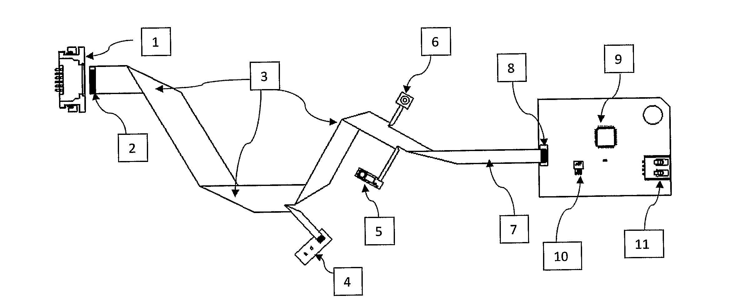
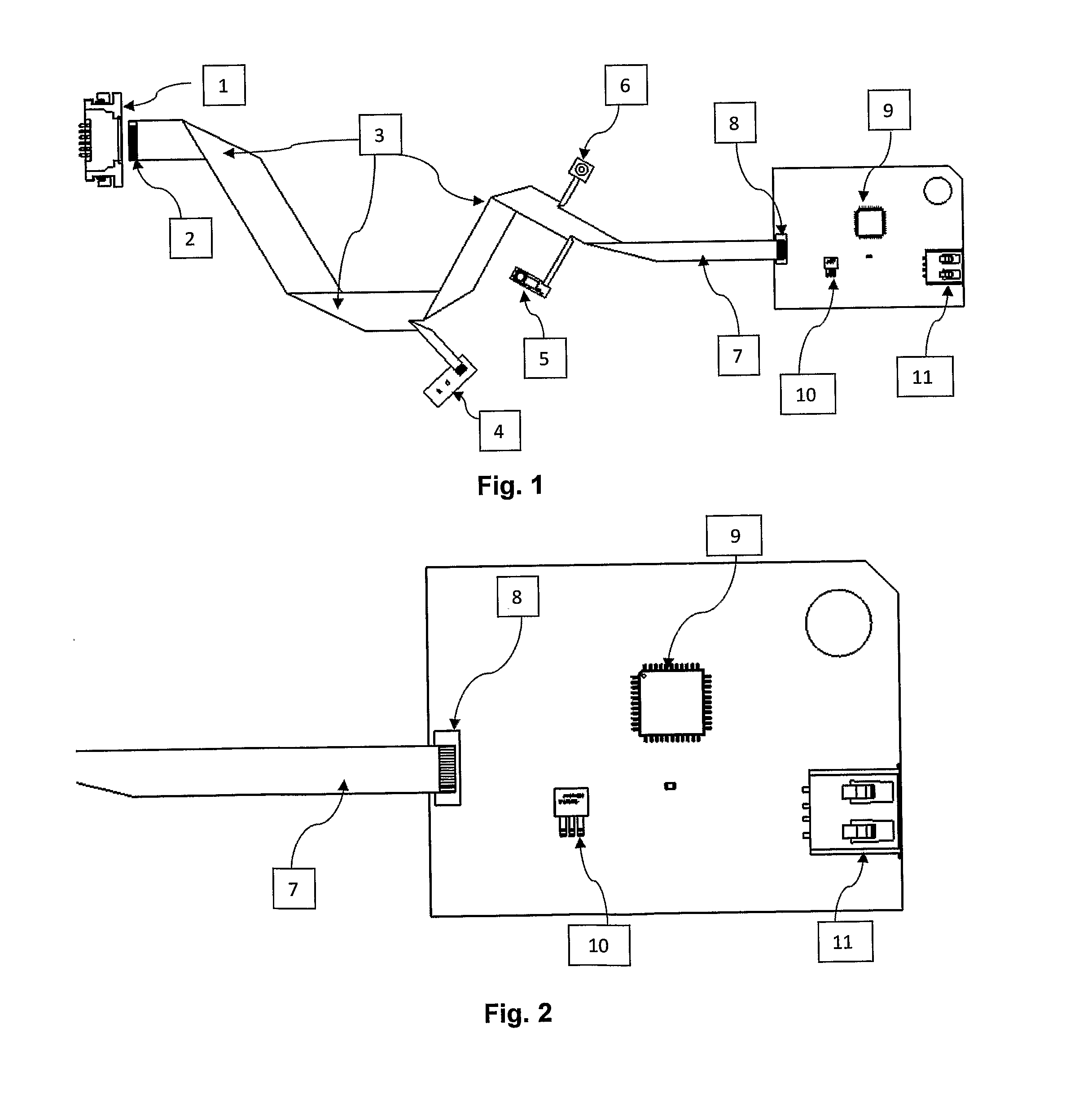
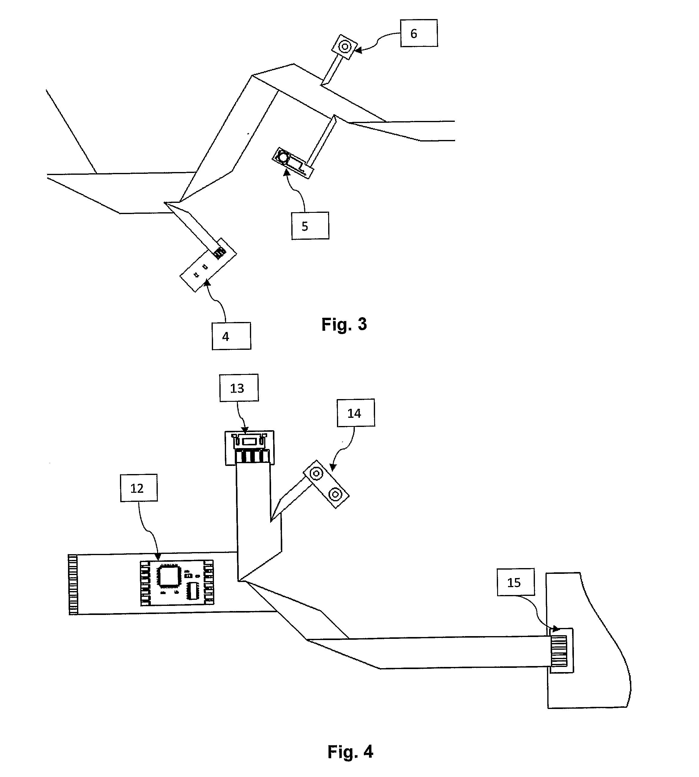
[0027]A preferred embodiment for the disclosed rigid-flex circuit board utilizing an improved flexible flat cable showing various extensions for connections and terminated with several circuit boards can best be appreciated by referring to FIGS. 1 to 3. The flexible flat cable end 2 is the contact pads preferably laminated with a layer of stiffener for inserting to connector 1. The flexible flat cable can be folded into different angles 3 customized to each specific application. The cable extension 4 is connected to a small printed circuit board mounted with light emitting diodes. A miniature tact switch is mounted on another group wires extension connected to printed circuit board 5. One extension of the cable is directly soldered to a stamped metal plate 6 for convenient screwed to grounding contact. The other end of the rigid-flex circuit board 7 is connected by soldering to another printed circuit board 8. This circuit board is mounted with a microcontroller 9, a transistor 10 a...


PUM

PropertyMeasurementUnit
flexibleaaaaaaaaaa
widthaaaaaaaaaa
sizeaaaaaaaaaa

Abstract

Disclosed herein is a cost effective rigid- flex circuit board comprising a flexible section which contents at least one flexible flat cable for interconnect, and a plurality of rigid sections which consists of at least one rigid printed circuit board (8) for components mounting. The improved flexible flat cable comprising at least one layer of flat wires laminated with a plurality of insulating material. The flat wires having non-uniform width and pitch are folded with different angle along the length to resemble wiring patterns of a typical flexible printed circuit board. The rigid section consists of at least one piece of rigid printed circuit board having at least one layer of circuit pattern.

Description

BACKGROUND OF THE INVENTION[0001]The present invention is related to the field of printed circuit boards, and in particular to the structure and manufacturing method of a cost effective rigid-flex circuit board comprising an improved flexible flat cable and a plurality of rigid printed circuit boards.[0002]Rigid-flex circuit boards and flexible printed circuit boards (FPC) are commonly used as reliable platforms for interconnecting and mounting components on circuits. Particularly, these circuit boards are used in handheld electronic products to alleviate the stringent weight and volumetric requirements. The construction of existing rigid-flex circuit boards is made by combining rigid printed circuit boards and FPCs which primarily utilize polyimide insulating material. Typical applications are found in mobile phones, laptop computers, digital cameras, optical disc drives and MP3 players.[0003]However, there are many problems associated with the structure and fabricating method of e...

Claims


Application Information

Patent Timeline
Patent Type & Authority Applications(United States)
IPC IPC(8): H05K1/02H01R43/16
CPCH05K1/118H05K1/147H05K1/148H05K3/363Y10T29/49204H05K2201/055H05K2201/09727H05K1/0278H01R43/16H05K2201/052
Inventor LI, HUI HONG JIM KERY
Owner DIGIPAS TECH INC
Why Eureka
Try Eureka