Plasma processing apparatus and method

a processing apparatus and technology of plasma, applied in the field of plasma processing apparatus and method, can solve the problems of reducing productivity, affecting the production of fine particles, and affecting the quality of plasma, and achieve the effect of suppressing the generation of fine particles

Active Publication Date: 2013-06-27
TOKYO ELECTRON LTD +1
View PDF11 Cites 152 Cited by
  • Summary
  • Abstract
  • Description
  • Claims
  • Application Information

AI Technical Summary

Benefits of technology

[0028]As described above, in accordance with the present invention, it becomes possible to suppress the generation of fine particles during the plasma processing in which a gas including a halogen-containing gas and an oxygen gas is introduced.

Problems solved by technology

Therefore, a generation of a fine particle having a size, which has been treated as being nonproblematic in a conventional plasma processing, has become problematic.
Hence, a region where designed electrical characteristics are not obtained is generated in the wafer, which leads to a decrease in productivity.
Further, the technical background of the recent miniaturization technique is completely different from that of Patent Document 1 that has been published more than ten years ago, because the pattern, which is micro-processed in conformity with the recent demand, cannot be formed by the pattern forming technique of Patent Document 1.
Therefore, in the case of supplying a plasma gas containing a gas including a CF-based gas and other gases into the chamber, Patent Document 1 does not provide the solution for preventing fine particles from causing a so-called killer defect by suppressing the generation of the fine particles each having a size of about 60 nm or less.

Method used


Image

  • Plasma processing apparatus and method
  • Plasma processing apparatus and method
  • Plasma processing apparatus and method

Examples


first embodiment

[0062]

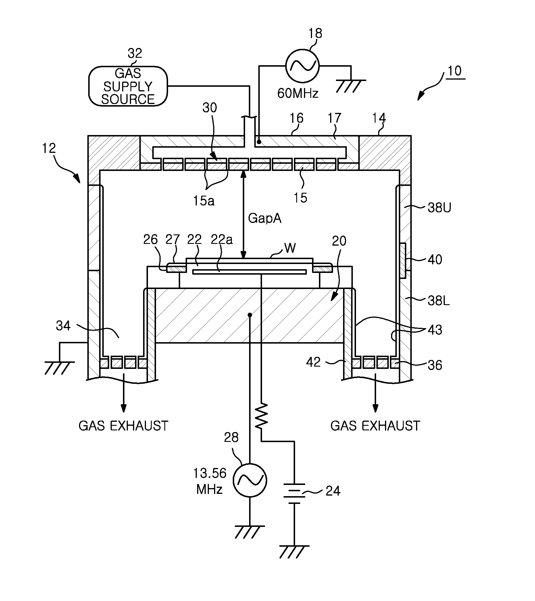
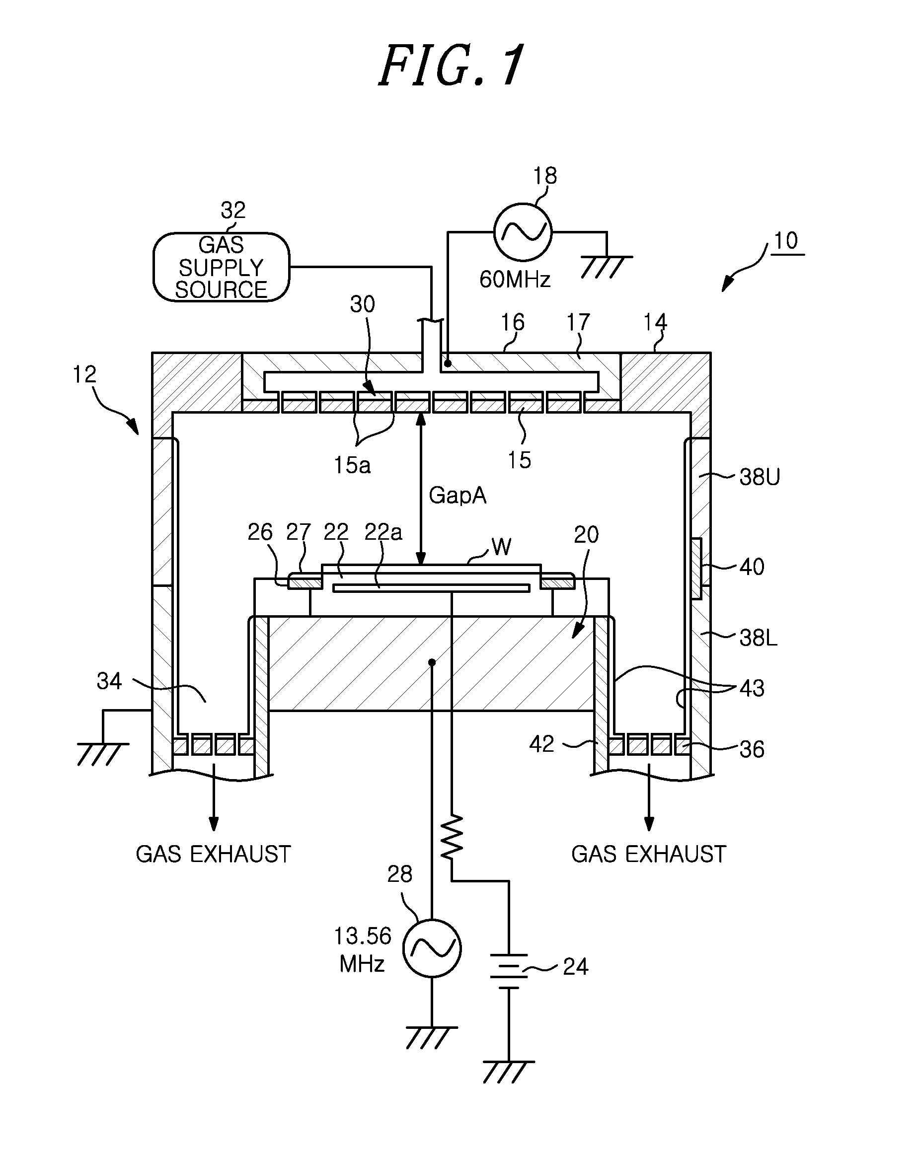
[0063]First, with reference to FIG. 1, there will be described a schematic configuration of a plasma processing apparatus 10 in accordance with the first embodiment of the present invention. FIG. 1 is a vertical cross sectional view showing a schematic configuration of the plasma processing apparatus 10 in accordance with the first embodiment.

[0064]The plasma processing apparatus 10 includes a cylindrical processing chamber 12 made of metal, e.g., aluminum, stainless steel or the like. The processing chamber 12 is grounded. The processing chamber 12 has an upper opening, and an upper electrode 16 is provided at the upper opening via an insulator 14. Accordingly, a cover portion is formed to cover the opening of the processing chamber 12. Further, the upper electrode 16 includes: an electrode plate 15 having a plurality of gas openings 15a in a surface opposite to the mounting table 20 and an electrode support body 17 to which the electrode plate 15 is detachably attached. The ...

second embodiment

[0113]

[0114]Next, a schematic configuration of a plasma processing apparatus 50 in accordance with a second embodiment of the present invention will be described with reference to FIG. 10A. FIG. 10A is a vertical cross sectional view showing a schematic configuration of the plasma processing apparatus 50 of the second embodiment. The plasma processing apparatus 50 of the second embodiment is configured as a magnetron RIE plasma processing apparatus, and includes a cylindrical processing chamber 52 made of metal, e.g., aluminum, stainless steel or the like. The processing chamber 52 is grounded.

[0115]In the processing chamber 52, the mounting table 60 for mounting thereon the wafer W is provided. The mounting table 60 is made of, e.g., aluminum, and supported in the processing chamber 52 via an insulating support member (not shown). Provided on a top surface of the mounting table 60 is an electrostatic chuck 62 for holding the wafer W by an electrostatic adsorptive force. The wafer W...


PUM


Abstract

A plasma processing apparatus includes a processing chamber; a lower electrode serving as a mounting table for mounting thereon a target object; and an upper electrode or an antenna electrode provided to be opposite to the lower electrode. The apparatus further includes a gas supply source for introducing a gas including a halogen-containing gas and an oxygen gas into the processing chamber and a high frequency power supply for applying a high frequency power for generating plasma to at least one of the upper electrode, the antenna electrode, or the lower electrode. Among inner surfaces of the processing chamber which are exposed to the plasma, at least a part of or all of the surfaces between a mounting position of the target object and the upper electrode, or the antenna electrode; or at least a part of or all of the surfaces of the upper electrode or the antenna electrode are coated with a fluorinated compound.

Description

CROSS-REFERENCE TO RELATED APPLICATIONS[0001]This application claims priority to U.S. Provisional Application 61 / 579,086 filed Dec. 22, 2011, and further claims priority to Japanese Application Numbers 2011-265897, filed Dec. 5, 2011 and 2012-259114, filed Nov. 27, 2012, the entire contents of each of which are hereby incorporated by reference.FIELD OF THE INVENTION[0002]The present invention relates to a plasma processing apparatus and method.BACKGROUND OF THE INVENTION[0003]Recently, a scaling-down has been in progress through a plasma processing, demanding for a line width of 20 nm or less to be formed on a wafer by an etching process. Therefore, a generation of a fine particle having a size, which has been treated as being nonproblematic in a conventional plasma processing, has become problematic. Particularly, for example, if the fine particle having a size of 60 nm or less falls onto a pattern formed on a wafer, a line having a line width of, e.g., 20 nm, becomes short-circuit...

Claims


Application Information

Patent Timeline
Patent Type & Authority Applications(United States)
IPC IPC(8): H05H1/46
CPCH05H1/46H01J37/32495H01J37/32477
Inventor NISHINO, MASARUMAKABE, MASATSUGUNAGAYAMA, NOBUYUKIHANDA, TATSUYAMIDORIKAWA, RYOTAROKOBAYASHI, KEIGONIYA, TETSUYA
Owner TOKYO ELECTRON LTD
Why Eureka
Try Eureka