Electrical energy storage cell and apparatus

a technology of energy storage cell and electric energy, which is applied in the direction of cell components, electrochemical generators, cell component details, etc., can solve the problems that lithium ion batteries (particularly secondary batteries) can produce considerable heat, and achieve the effects of reducing mechanical stresses, reducing mechanical stresses, and equalizing the heat balance of blocks

Inactive Publication Date: 2013-06-27
LI TEC BATTERY
View PDF3 Cites 20 Cited by
  • Summary
  • Abstract
  • Description
  • Claims
  • Application Information

AI Technical Summary

Benefits of technology

[0012]The heat-conducting element preferably exhibits an at least substantially planar, thin form. Such a heat-conducting element is particularly simple to manufacture, has a large heat transfer surface and low net weight. When the heat-conducting element essentially extends over the largest projected surface of the electrical energy storage structure, this also enables high absorption of heat from the electrical energy storage structure.
[0023]It is particularly preferred for the cooling structure to be designed and equipped to being cooled by means of a fluid, preferably a liquid, particularly water and / or an alcohol such as pure glycol or a glycol mixture. Liquid cooling also realizes an effective and efficient dissipating of the heat absorbed by the heat-conducting elements. The cooling structure is thereby preferably designed and adapted to connect to a coolant supply circuit so as to ensure efficient cooling of the apparatus.

Problems solved by technology

A lithium ion battery (particularly a secondary battery) can produce considerable heat when charging and discharging.

Method used


Image

  • Electrical energy storage cell and apparatus
  • Electrical energy storage cell and apparatus
  • Electrical energy storage cell and apparatus

Examples


Embodiment Construction

[0036]The following will reference the drawings in describing a preferred embodiment of the present invention and various modifications and embodiment variations thereof in greater detail. Identical or equivalent components or components of equal or equivalent action are thereby identified by the same or similar reference numerals.

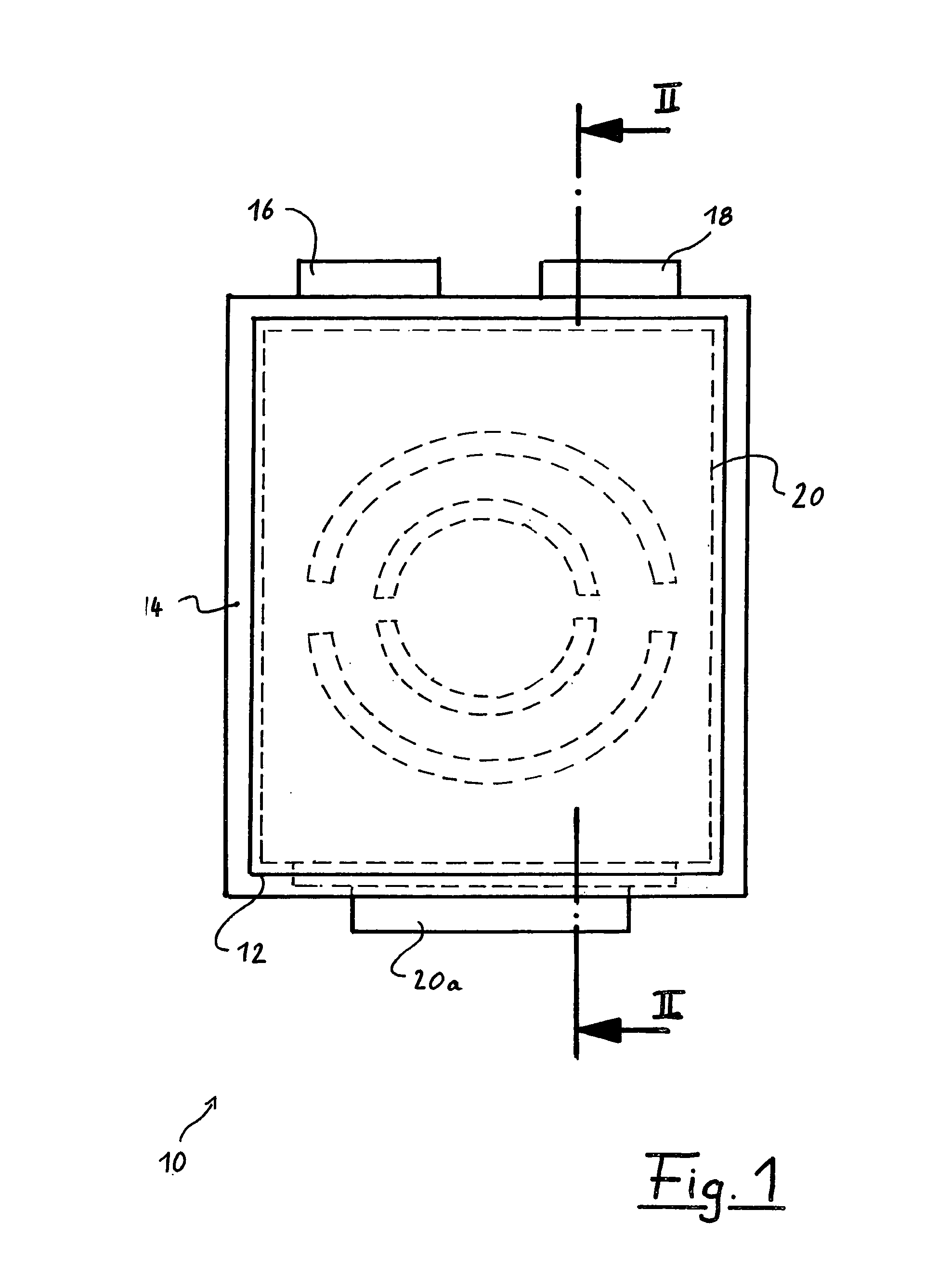
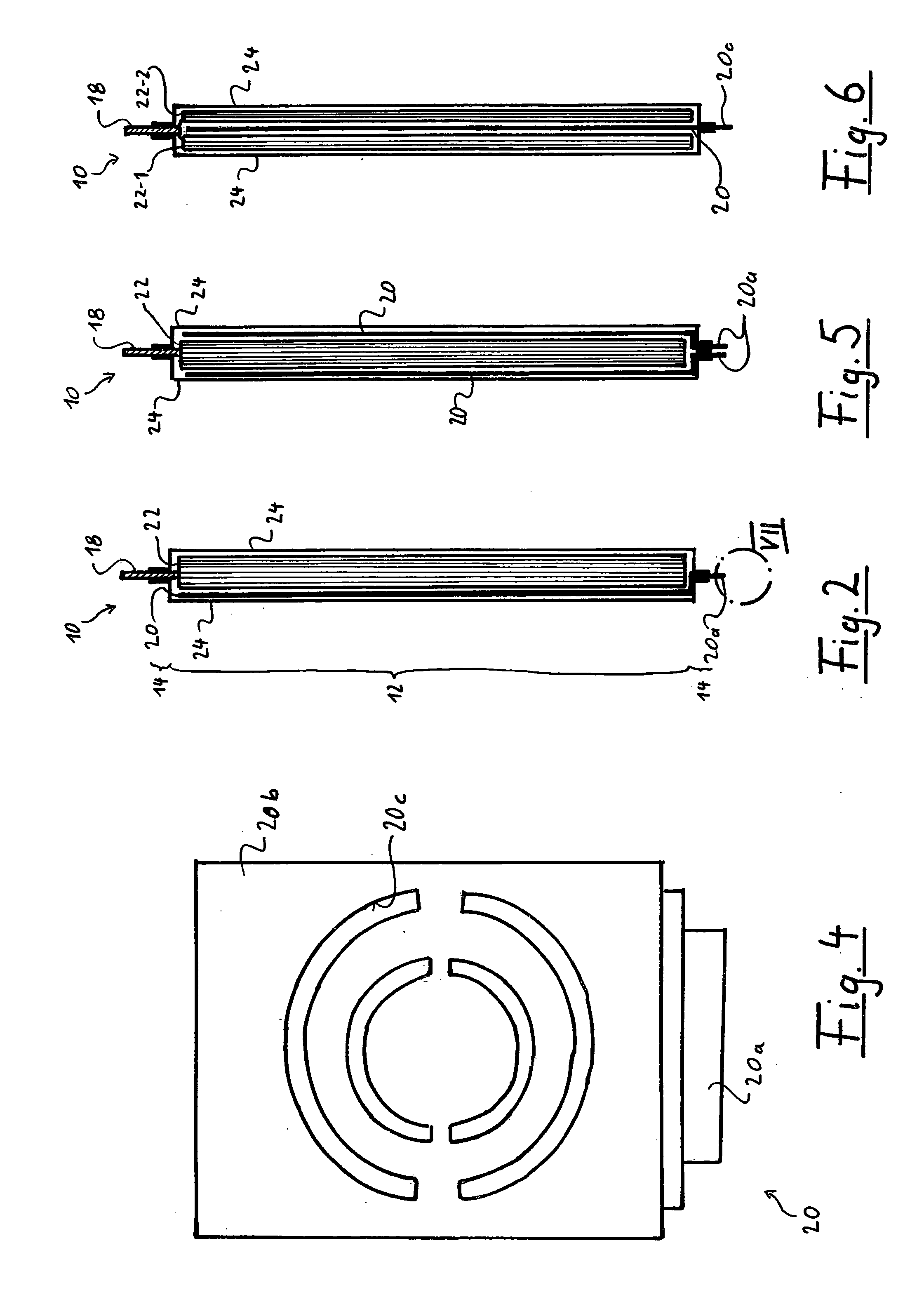
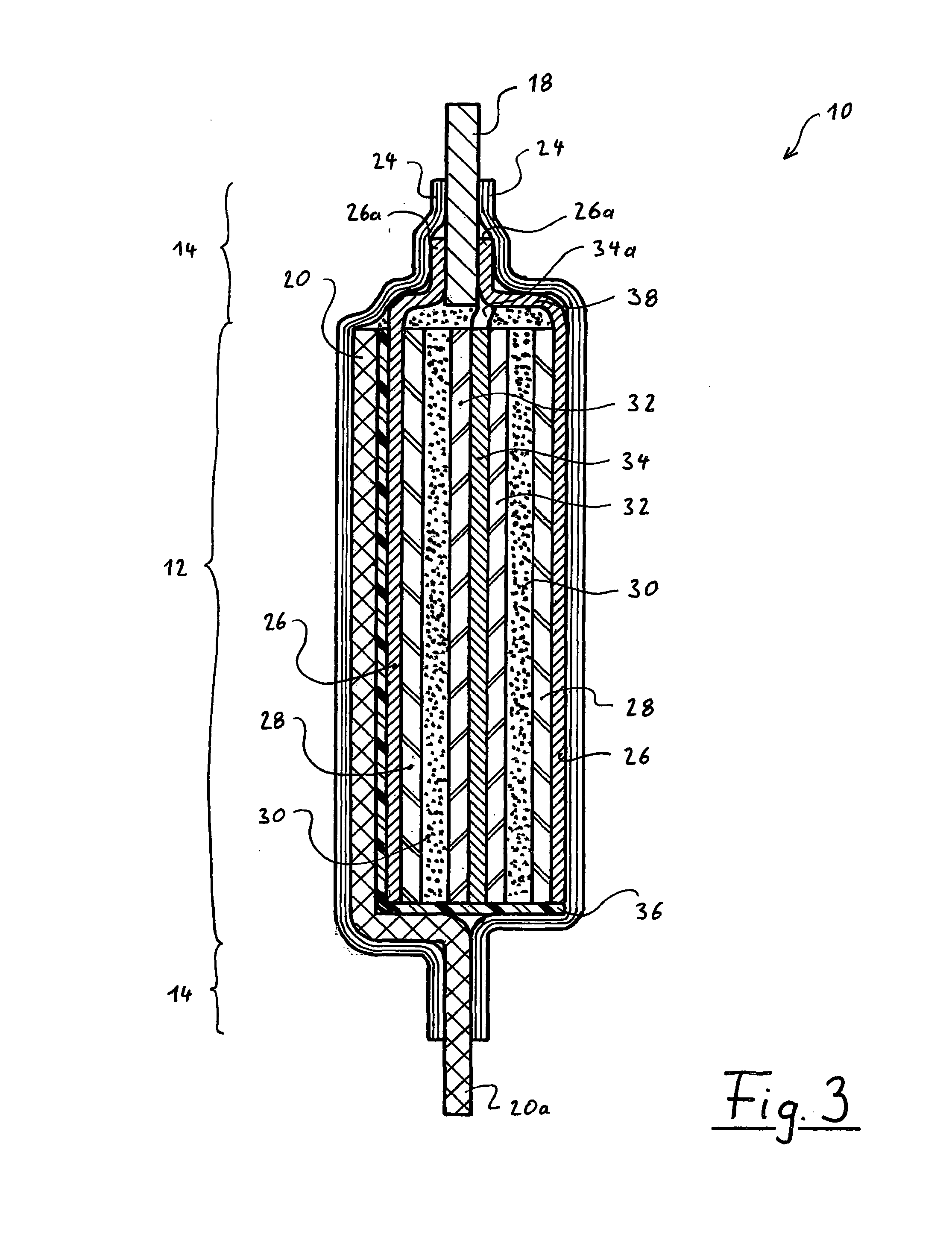
[0037]A basic embodiment of a battery cell of the present invention will first be described with reference to FIGS. 1 to 4. FIG. 1 thereby shows a frontal view of a battery cell 10 having a heat baffle plate 20; FIG. 2 shows a sectional side view of the battery cell 10 along the II-II line from FIG. 1; FIG. 3 is an enlarged depiction of the FIG. 2 sectional view exaggerated in the thickness direction in order to clarify the structure of the battery cell 10 in detail; and FIG. 4 shows just the heat baffle plate 20 in the same view as in FIG. 1.

[0038]The battery cell 10 in the present embodiment is a lithium ion accumulator cell of coffee bag or pouch type. ...


PUM

PropertyMeasurementUnit
thickaaaaaaaaaa
thicknessaaaaaaaaaa
thicknessaaaaaaaaaa

Abstract

The invention relates to an electrical energy storage cell comprising an electrical energy storage structure, a housing which receives the electrical energy storage structure and surrounds it in a sealed manner, and at least two contact elements which are accessible outside the housing for the electrical connection to electrode regions of the electrical energy storage structure. At least one heat conducting element, which is constructed separately from the electrical energy storage structure and is designed and equipped to absorb heat from the electrical energy storage structure and to release heat to outside of the housing, is disposed inside the housing. The invention also relates to an electrical energy storage device comprising an array of electrical energy storage cells.

Description

[0001]The present invention relates to an electrical energy storage cell in accordance with the precharacterizing part of claim 1 as well as an electrical energy storage apparatus having an array of electrical energy storage cells.BACKGROUND OF THE INVENTION[0002]Batteries (primary storage) and accumulators (secondary storage) for storing electrical energy are known which are composed of one or more storage cells in which when a charging current is applied, electrical energy is converted into chemical energy in an electrochemical charge reaction between a cathode and an anode in or between an electrolyte and thus stored and in which when an electrical load is applied, chemical energy is converted into electrical energy in an electrochemical discharge reaction. Primary storage devices are normally only charged once and once having been discharged, need to be disposed of, whereas secondary storage devices allow multiple charging and discharging (from a few 100 to more than 10,000 cycl...

Claims


Application Information

Patent Timeline
Patent Type & Authority Applications(United States)
IPC IPC(8): H01M10/50H01M50/548H01M50/55H01M50/557H01M50/562H01M50/566
CPCH01M2/021H01M2/0212H01M10/5004H01M10/5016H01M10/5075H01M10/5042H01M10/5053H01M10/5077H01M10/5044H01M10/5032H01M10/625H01M10/647H01M10/654H01M10/6568H01M10/6554H01M10/613Y02E60/10H01M50/557H01M50/55H01M50/548H01M50/566H01M50/562
Inventor ZAHN, CHRISTIAN
Owner LI TEC BATTERY
Why Eureka
Try Eureka